Understanding Welding Defects and Their Significance
Welding defects are irregularities that occur in welded joints which can compromise the structural integrity of a fabricating project. These imperfections can range from cracks and porosity to incomplete penetration and distortion, each with its own potential impact on the strength and durability of the weldment. Recognizing these defects is crucial since they often serve as focal points for stress concentration, leading to premature failure of the structure under service conditions. For engineers, welders, and inspectors, knowledge of common welding flaws, their root causes, and corresponding remedies is essential. It ensures not only the safety and reliability of welded structures but also contributes to minimizing costly rework and material wastage, thereby enhancing overall production efficiency.
Porosity in Vacuum Casting: Causes and Remedies
Porosity in vacuum casting refers to the formation of small voids or air bubbles within the material of a cast part. This phenomenon can significantly impact the mechanical properties and aesthetic quality of the final product. Understanding the causes and implementing effective remedies are crucial steps in minimizing porosity and ensuring the production of high-quality parts.
Causes of Porosity
The formation of porosity in vacuum casting can be attributed to several factors:
- Trapped Air in Resin: Air can become trapped within the casting resin during the mixing process or if the resin is poured too quickly into the mold.
- Insufficient Venting: Inadequate venting in the mold design can prevent air from escaping as the resin is poured, leading to air entrapment.
- Inconsistent Resin Mixing: Failure to mix the resin consistently can result in areas of different viscosities, which can trap air.
- Extreme Resin Temperature Variations: Significant fluctuations in resin temperature during the casting process can cause air bubbles to form.
Remedies for Porosity
To mitigate the effects of porosity and prevent its occurrence, several strategies can be employed:
- Optimizing Mold Venting: Ensuring proper venting channels within the mold allows air to escape, reducing the likelihood of air entrapment.
- Degassing the Resin: Removing trapped air from the resin before casting through degassing techniques can significantly reduce porosity.
- Consistent Resin Mixing: Maintaining uniform resin viscosity through consistent mixing helps prevent air bubble formation.
- Monitoring Resin Temperature: Controlling the temperature of the resin during casting can prevent the formation of air bubbles due to thermal variations.
Real-World Examples and Solutions
In practical applications, addressing porosity requires a combination of careful planning, precise execution, and ongoing quality control. For instance:
- Aerospace Components: Porosity issues in aerospace interior components were resolved by optimizing mold venting, adjusting casting resin viscosity, and implementing rigorous post-casting inspections.
- Consumer Electronics: Surface irregularities in housings for consumer electronic devices were improved by adjusting mold design and selecting resin with improved flow properties, coupled with strict post-casting visual inspections.
- Medical Devices: Inconsistent dimensions and failed bio-compatibility tests in complex components for medical devices were addressed through advanced in-line monitoring during the casting process, including real-time temperature control and pressure sensing.
Cracks: Causes and Remedies in Welding
In welding, cracks are serious defects that can jeopardize the structural integrity of the welded assembly. They may manifest as hot cracks, which occur at high temperatures during solidification of the weld metal, or as cold cracks that develop once the weld has cooled due to residual stresses and metallurgical changes. These failures often result from rapid cooling rates, unsuitable joint design, or material impurities. To minimize the risk of cracking, it is recommended to preheat metals when necessary to slow down the cooling process, ensure a proper joint fit-up and welding technique, and carefully select materials and filler metals compatible with the base metal’s thermal expansion properties. For instance, controlling the heat input by adjusting the welding parameters can avoid excessive temperature gradients that lead to hot cracking.
Undercutting: Identification and Solutions
Undercutting is a weld defect characterized by a groove that forms at the base of the weld bead, adjacent to the plate or pipe surface. This flaw compromises the integrity of the joint by creating areas with reduced cross-sectional thickness which can lead to potential points of failure under stress or fatigue. A primary factor contributing to undercutting is the use of high current settings during welding, as they may cause excessive melting of the metal edges. To prevent this issue, welders must select appropriate current levels based on the material and thickness being welded. Additionally, employing a proper welding technique with consistent travel speed helps in avoidance. Should an undercut occur, repair methods typically involve grinding out the defect and re-welding, ensuring that factors such as heat input and electrode angle are controlled to produce a sound, defect-free joint.
Incomplete Fusion: Understanding and Addressing the Issue
Incomplete fusion in welding is a defect where materials to be joined are not adequately fused. This occurs when the weld metal does not fully merge with the base material or previous pass of the weld, leading to weak joints that may fail under stress. Several factors contribute to poor fusion, including incorrect welding techniques, improper angle or speed of the welding gun, insufficient heat input, and unclean workpieces. To combat incomplete fusion, welders must apply appropriate heat settings, ensure surfaces are clean and free from contaminants, maintain proper electrode angles, and precisely control travel speed during the welding process. A key strategy is pre-heating of the workpiece to the correct temperature, which can significantly reduce the risk of this flaw by promoting better metal flow and allowing more time for the fusion of materials.
Slag Inclusions: Detection and Avoidance
Slag inclusions refer to non-metallic solid material entrapped in the weld metal or between the weld metal and base metal, often originating from the flux used during the welding process. These are typically caused by improper cleaning procedures between passes that allow slag, a byproduct of the flux, to remain embedded within the resulting weld. To prevent such inclusions, it is essential to thoroughly clean the weld area after each pass, ensuring any remnants of slag are removed before subsequent layers are added. Welders can employ techniques like wire brushing or grinding for effective slag removal. Furthermore, maintaining an appropriate angle and speed with the electrode can minimize the formation of slag throughout the welding process.
Spatter: Examination and Reduction Techniques
Spatter in welding refers to the droplets of molten material that are expelled from the welding area during the joining process, often adhering to the surrounding surface as unintended dots or splashes. It occurs due to a volatile weld pool, commonly caused by high amperage, an incorrect angle of the welding torch, or impurities in the materials being joined. Factors such as improper shielding gas flow rate, inappropriate electrode size, and inconsistent welding techniques can all amplify spatter occurrence. To mitigate spatter, it’s crucial to maintain clean work surfaces and adjust equipment settings to optimal levels, ensuring appropriate travel speed and orientation of the torch. Using anti-spatter agents can also be effective, along with regularly checking for proper wire feed performance and utilizing pulsing welding technology when possible. These practices contribute significantly to achieving smoother welds with minimal cleaning requirements post-weld.
Incomplete Penetration: Recognition and Prevention
In the realm of welding, incomplete penetration occurs when the weld metal fails to occupy the entire joint thickness, leaving an unfused void along the joint line. Typically, this defect arises from incorrect welding parameters such as low heat input or insufficient speed control. Additionally, it can be due to improper joint design or fit-up. To achieve full penetration, a welder should ensure that the angle and position of the welding torch are optimal and maintain consistent travel speeds throughout the process. For instance, in butt joints, the correct gap between pieces is crucial for allowing the weld metal to fully reach the root of the joint. It’s also essential to adjust power settings on the welding machine according to the material thickness to facilitate adequate heat delivery. By adhering to these techniques, proper fusion across the entirety of the joint interface can be secured.
Overlap: Issues and Rectification Approaches
An overlap defect in welding occurs when the molten metal flows over the surface without fusing with the base metal, leading to a weak joint. This typically arises under high heat input or incorrect travel speed, where the weld pool becomes excessively fluid and spreads beyond intended bounds. To prevent overlaps, precise control of welding parameters is crucial, such as adjusting the welding current, voltage, and travel speed to ensure proper fusion. Additionally, maintaining a consistent angle and electrode positioning helps to distribute the heat evenly, reducing the propensity for overlapping material. When identifying an overlap, look for irregularities on the toe of the weld that do not blend smoothly with the parent metal. Skilled welders also minimize the risk by practicing proper technique and attentively monitoring the weld bead’s appearance during application.
Analysis of Less Common Welding Flaws: Burn Through Details and Prevention Tactics
Burn through is a welding flaw where excessive heat causes the material to melt and create a hole. This problem typically arises when working with thin materials or if the welder applies too much heat or speed during the process. Variables that can lead to burn through include high amperage settings, improper torch angle, and lack of proper heat distribution across the workpiece. To prevent this issue, it’s essential to use lower heat inputs, adjust weld speed accordingly, and employ techniques like pulse welding to moderate the penetration and buildup of heat. Keeping the torch moving and avoiding prolonged exposure in one spot is also critical for preventing burn through on delicate surfaces.
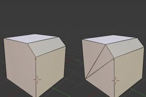
Excessive Convexity or Concavity: Measurement and Correction
When dealing with sheet metal parts, the presence of excessive convexity or concavity can significantly impact the part’s overall appearance, structural integrity, and functionality. Understanding how to measure and correct these features is crucial in maintaining the quality and performance of the part. Below, we outline the key considerations and steps for addressing excessive convexity or concavity.
Measurement of Convexity or Concavity
- Identify the Affected Area: Begin by visually inspecting the part for areas of excessive convexity or concavity.
- Use Appropriate Tools: Utilize tools such as calipers or depth gauges to measure the depth or height of the feature accurately.
- Compare Against Specifications: Measure the feature’s dimensions against the design specifications to determine if it falls within acceptable tolerances.
Correction Strategies
For Excessive Concavity:
- Adjusting Depth: Ensure that the depth of concave features does not exceed 50% of the sheet metal thickness to avoid stress concentration.
- Placement and Size: Concave features should be strategically placed where they offer the most benefit and sized appropriately for the application.
- Tool Selection: Choose the right tools for creating concave features, such as punches, dies, and forming tools, based on the size and shape of the concavity and the material type.
For Excessive Convexity:
- Maintaining Wall Thickness: Keep the wall thickness consistent to avoid issues. Use internal radius curves to distribute thermal stress and consider the effect of gravity on wall thickness.
- Smooth Transitions: Use fillets to smooth the transition between convex features and surrounding materials, helping to distribute stress more evenly.
- Correct Sizing and Placement: Carefully consider the size and placement of convex features to ensure they provide necessary support and strength without interfering with other components or creating manufacturing challenges.
General Considerations
- Material Thickness: The thickness of the material can influence the size and shape of convex and concave features. Thicker materials may require larger or deeper features to provide the necessary strength and rigidity.
- Avoid Weak Points: Do not place convex or concave features too close to each other or near bends, as this can create weak points in the material.
- Stress Distribution: Use larger radii for fillets to distribute stress more evenly and reduce the likelihood of stress concentration.
- Design Limitations: Ensure that the design considers any potential issues or challenges that adding convex or concave features might introduce.
By carefully measuring and correcting excessive convexity or concavity, manufacturers can ensure that sheet metal parts meet all functional and aesthetic requirements. This involves a balanced approach to design, material selection, and manufacturing techniques to achieve the desired outcome without compromising the part’s integrity.
Concluding Remarks on Welding Defects
In surveying welding defects, we have traversed a spectrum of common issues that can undermine the integrity and performance of welded structures. From porosity’s bubble-like intrusions to crack formations’ menacing fissures, each defect bears testimony to potential pitfalls in the welding process. The causes are as varied as the defects themselves—the precise control of heat input, contamination avoidance, and adherence to proper technique being essential to their prevention. To forge ahead in the reduction of such imperfections, welders must engage in ongoing education, honing skills to foster an environment where meticulous practice is not just encouraged but seen as vital. Remedies often demand a keen eye for detail: frequent inspection, rigorous pre-weld preparation, and post-weld treatments assert themselves as cornerstones in sustaining the structural safety and longevity of welded components.
Other Articles You Might Enjoy
- Hastelloy vs. Stainless Steel in Chemical Processing Equipment: CNC Machining Perspectives?
Hastelloy vs. Stainless Steel in Chemical Processing Equipment: An Introduction In the realm of chemical processing equipment, two commonly used materials include Hastelloy and stainless steel. Hastelloy, a reputed superalloy…
- Mastering Rivets and Tack Welding in CNC Machining( spot welding Marsh)
Computer numeric control (CNC) machining represents an exciting world of precision, consistency, and robust capabilities that have reshaped countless industries. Two operations playing highly significant roles within this domain are…
- The Viability of Magnesium Alloys in Lightweight CNC Machined Components: Benefits and Challenges?
Introduction to Magnesium Alloys and CNC Machining Magnesium alloys, due to their lightweight nature coupled with superior mechanical properties, have been gaining prominence in various manufacturing industries. In particular, the…


