Overview of Metal Cutting Machine Tools
Metal cutting machine tools are machines that use tools or abrasives to cut metal workpieces. They are known as the “mother machines,” the machines that make other machines. The development of China’s mechanical manufacturing technology, especially cold processing technology, is continuously improving and expanding. It is moving towards high precision and automation, driving the practical application and production of “precision engineering” and “nanotechnology.”
Types of Machine Tools
Machine tools are mainly divided into the following categories based on the processing method and the tools used:
- Lathe: Used for machining various rotating surfaces and the end faces of rotating bodies. Some can also machine threaded surfaces. The main movement is achieved by the rotation of the workpiece, while the feed movement is completed by the linear movement of the tool.
- Grinding Machine: Uses abrasives and grinding tools to perform surface grinding on workpieces, widely used for fine machining of parts, especially hardened parts and high-hardness special materials.
- Drilling Machine: A hole processing machine tool that uses a drill bit to machine holes in workpieces, usually for small-sized holes with low precision requirements.
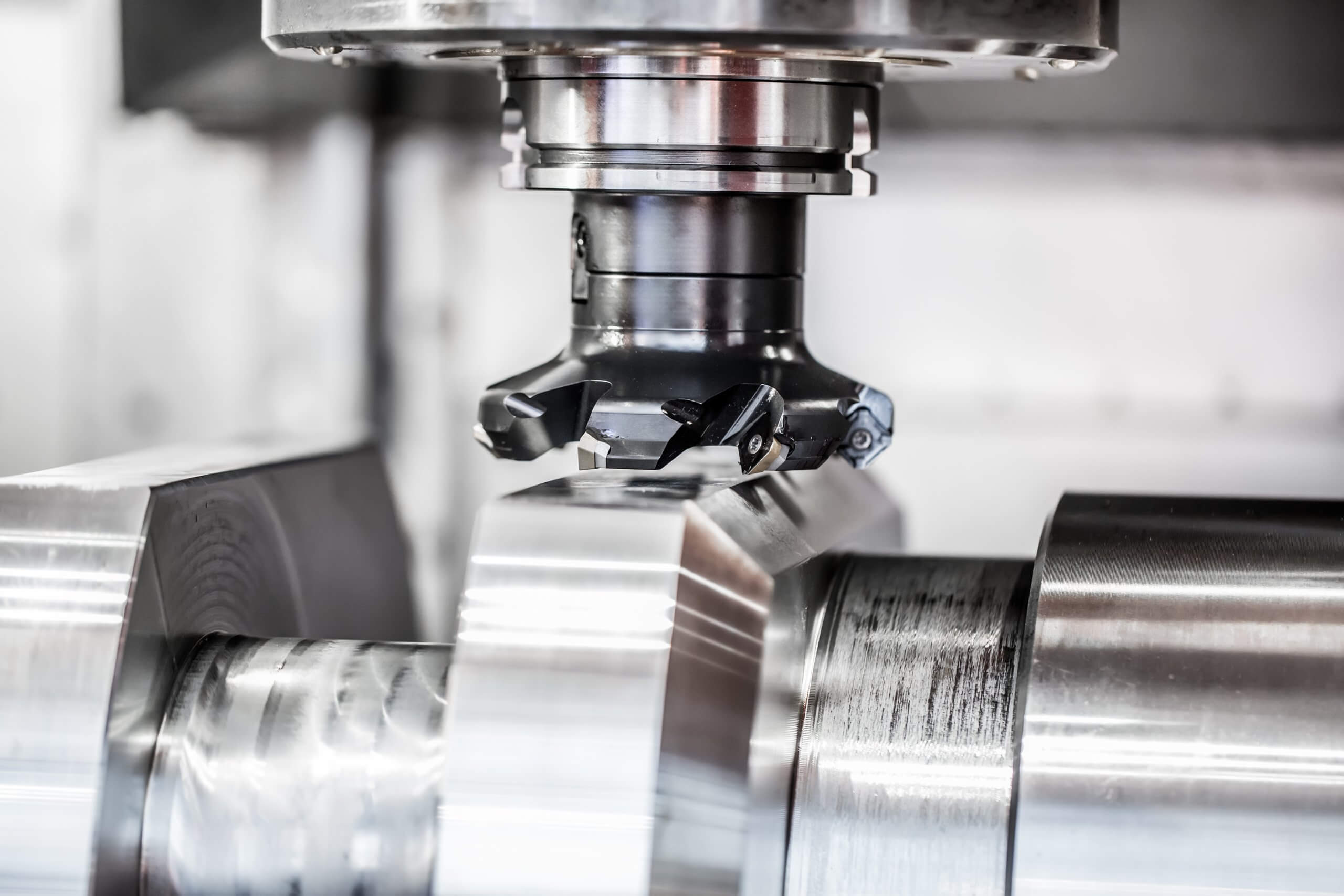
- Milling Machine: Uses a milling cutter for cutting operations, capable of machining planes, grooves, teeth on multi-tooth parts, spiral surfaces, and various curves. It has a wide range of applications.
- Boring Machine: Mainly uses a boring tool to machine holes in workpieces, suitable for larger holes with high precision requirements.
- Planer: Mainly used for planing various planes and grooves.
- Slotting Machine: Mainly used for machining the inner surface of workpieces, and sometimes for forming inner and outer surfaces.
- Gear Processing Machine: Used for machining the teeth of gears.
Design Requirements for Machine Tools
The performance of machine tools is 80% determined during the design phase, making the application of design methods and tools crucial. The design of machine tools needs to meet the following requirements:
- Process Range: Meet various processing needs.
- Productivity and Automation: Improve production efficiency and adapt to automated production.
- Machining Accuracy and Surface Roughness: Ensure processing quality.
- Reliability: Ensure the stability and durability of the machine tool.
- Mechanical Efficiency and Lifespan: Optimize design to enhance lifespan.
- Noise: Control noise pollution to improve the working environment.
Design Methods for Machine Tools
Machine tool design has evolved from static analysis to dynamic analysis, from qualitative analysis to quantitative analysis, from linear analysis to nonlinear analysis, from safety design to optimized design, and from manual design to automated design. The main design methods include a combination of theoretical analysis and experimental research.
Overall Design of Metal Cutting Machine Tools
Principle of Machine Movement
In cutting processes, to obtain workpieces with specific geometric shapes, accuracy, and surface quality, the tool and the workpiece must complete a series of movements. These movements can be divided into two main categories: surface forming movements and auxiliary movements:
- Surface Forming Movements: Directly participate in the cutting process, creating a specific geometric surface on the workpiece through relative movements between the tool and the workpiece. Surface forming movements include main movements and feed movements.
- Main Movement: Causes the tool to approach the workpiece to achieve cutting.
- Feed Movement: Provided by the machine or manually to ensure continuous cutting.
- Auxiliary Movements: All movements other than surface forming movements that are necessary to achieve various auxiliary actions during the machining process.
Principle of Machine Transmission
The transmission system of the machine tool must include actuators, power sources, and transmission elements. Transmission chains are divided into external and internal transmission chains:
- External Transmission Chain: Connects the power source and the machine tool actuator, enabling the actuator to move and change speed and direction.
- Internal Transmission Chain: Connects the components within the composite movement, requiring precise relative speed between the actuators to ensure the motion trajectory.
Overall Structural Scheme of Machine Tools
The structural layout of machine tools includes vertical, horizontal, and inclined forms; base support forms include base type, column type, and gantry type; the structure of base support parts includes integrated and separated types. During design, commercialized functional components should be chosen as much as possible to improve performance and shorten the manufacturing cycle.
Design of the Main Transmission System
Classification and Transmission Methods of the Main Transmission System
The main transmission system is classified based on the type of motor, transmission device, and the continuity of speed change:
- Centralized Transmission Method: All transmission and speed change mechanisms are concentrated in a single spindle box, commonly used in general-purpose machine tools.
- Separated Transmission Method: Most of the transmission and speed change mechanisms are housed in a separate gearbox away from the spindle and transmitted to the spindle box via belt transmission.
Design of the Stepped Speed Change Main Transmission System
Design steps include drafting the structure, drawing the speed diagram, and distributing transmission ratios. The speed diagram displays the number of transmission shafts, their relationships, spindle speed values, transmission routes, speed gradations, and transmission ratios.
Design of Infinitely Variable Speed Main Transmission System
Infinitely variable speed refers to the ability to continuously change speed within a certain range, achieving the most favorable cutting speed. Commonly used devices include variable speed motors, mechanical infinitely variable transmission devices, and hydraulic infinitely variable transmission devices.
Design of the Feed Transmission System
Characteristics of the Feed Transmission System
The design of the feed transmission system should consider feed rate, torque transmission, stiffness, transmission accuracy, etc. Additionally, the feed movement speed is generally low, the required power is small, but the number of feed movements is high, as seen in horizontal boring machines.
Design Principles for Feed Motion Transmission Systems
The principles include:
- Ensuring the specified feed rate.
- Transmitting the required torque.
- Having sufficient static and dynamic stiffness.
- Ensuring transmission accuracy.
- Ensuring smooth and sensitive movement for low-speed micro-feed systems.
- Compact structure, easy operation and maintenance.
Design Features of Mechanical Feed Transmission Systems
Mechanical feed transmission systems include a power source, speed change system, reversing mechanism, motion distribution mechanism, safety mechanism, linear motion mechanism, and manual operation mechanism. The design should ensure rational configuration of transmission parts, speed regulation range, and transmission accuracy.
Electrical Servo Feed System
Electrical servo systems are divided into open-loop, closed-loop, and semi-closed-loop systems based on the presence of detection and feedback devices. Servo system drive components, such as stepper motors, DC servo motors, and AC servo motors, control the feed movements of each coordinate axis of the machine tool.
Mechanical Transmission Components in Electrical Servo Feed Systems
Mechanical transmission components should meet the requirements for low friction transmission, use of ball screw nut transmission, matching between servo system and mechanical transmission system, selection of the optimal reduction ratio, and methods for eliminating transmission backlash.
Data Table
| Machine Tool Type | Code | Main Function |
|---|---|---|
| Lathe | C | Machining rotating surfaces |
| Grinding Machine | M | Surface grinding |
| Drilling Machine | Z | Hole processing |
| Milling Machine | X | Cutting operations |
| Boring Machine | T | Machining high-precision holes |
| Planer | B | Planing surfaces |
| Slotting Machine | I | Machining inner surfaces |
| Gear Processing Machine | G | Machining gear teeth |
Through the above content, we have gained an in-depth understanding of the principles and applications of metal cutting machine tool design. We hope that, based on these principles, you can better apply them to practical mechanical design and manufacturing.
Other Articles You Might Enjoy
- Comprehensive Guide to Metal Cutting Tools
In modern mechanical manufacturing, metal cutting processes are the most widely used methods, accounting for over 50% of the total workload in mechanical manufacturing. Whether it's a conventional lathe, an…
- From Vision to Reality: CNC Machining for Custom Furniture Design
Introduction to CNC Machining in Custom Furniture Design The advent of computer numerical control (CNC) machining has revolutionized the field of custom furniture design, allowing precise and intricate patterns to…
- Mastering the Removal of Chrome from CNC Machined Metal( cnc machine tools Bevis)
CNC machining continually manifests itself as a revolution in the world of manufacturing, demonstrating its potential to generate precise and complex parts. Given this great reputation, it has made strides…
- The Art of Bead Blasting in CNC Machining(cnc laser cutting machine Cyril)
Bead blasting is a finishing process frequently used in many industries, including the world of Computer Numerical Control (CNC) machining. It involves forcefully propelling a stream of abrasive bead material…
- CNC Machining of Rare Earth Metals: Opportunities and Challenges in Modern Manufacturing?
Introduction to CNC Machining CNC machining, also known as Computer Numerical Controlled machining, is a critical manufacturing process employed across various industries today. This technique involves the use of computers…
- Custom CNC Machining for Advanced Prosthetic Devices
Introduction: Prosthetic Devices & Custom CNC Machining Prosthetic devices are artificial components designed to replace a missing or impaired part of the body, thereby enhancing mobility and functionality for an…


