Introduction
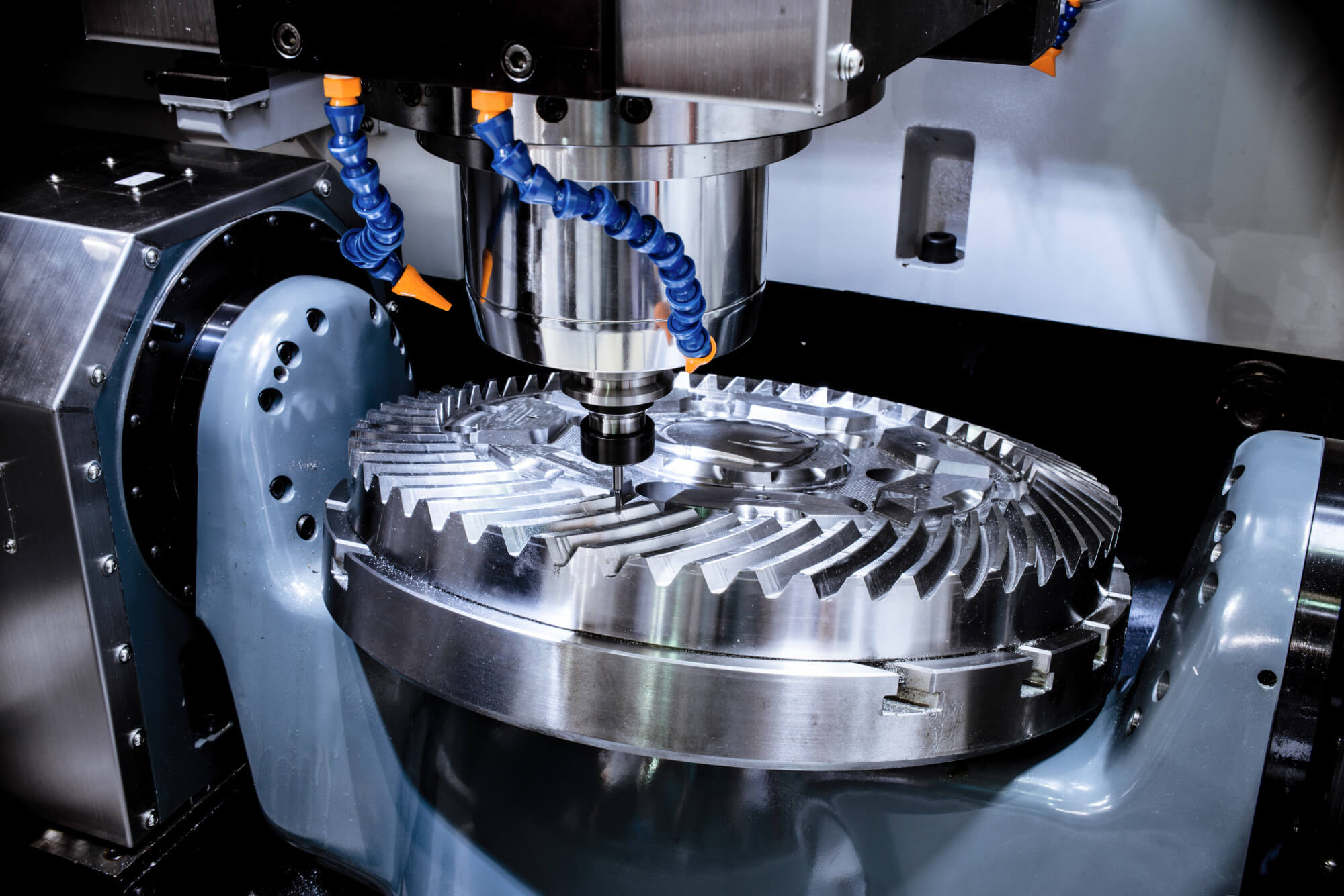
Aluminum alloy frame parts are like the unsung heroes of the aerospace industry. These components, found in aircraft frames, beams, and bulkheads, are critical for ensuring structural integrity and performance. However, machining these large, complex parts can be a nightmare due to deformation issues. Imagine working on a piece that starts out weighing 550 kg and ends up just 10.1 kg after machining! The high material removal rate and the subsequent thin walls (sometimes only a few millimeters thick) pose significant challenges. Let’s dive into the world of CNC machining and explore how finite element simulation can help us understand and manage the deformation of these aluminum alloy parts.
Why Deformation Happens
Deformation in machining is a common issue, especially for large, integral structures. The primary culprits are cutting forces, cutting heat, and residual stresses. Here’s a quick rundown:
- Cutting Forces: These forces can cause the part to deflect during machining. Once the cutting force is removed, the elastic deformation might lead to dimensional errors.
- Cutting Heat: Heat generated during machining can cause thermal expansion, leading to deformation.
- Residual Stresses: These stresses, inherent in the material or induced during machining, can cause warping once the part is released from the fixture.
Cutting Forces and Deformation
Cutting forces are inevitable in CNC machining. They can lead to what’s known as “spring-back” or elastic recovery, where the part tries to return to its original shape after the cutting force is removed. To mitigate this, several strategies can be employed:
- Auxiliary Supports: Using supports during machining can help reduce deflection.
- Repeat Passes in Finishing: By taking lighter, repeated cuts during finishing, the cutting force impact can be minimized.
- High-Speed Machining: This technique can reduce cutting forces and improve surface quality.
Cutting Heat and Deformation
Heat is another major player in the deformation game. Managing heat through effective cooling can help maintain dimensional accuracy:
- Increased Cooling: Using more coolant can help keep the part and tool cool, reducing thermal expansion.
- High-Speed Cutting: This not only reduces cutting forces but also minimizes the time heat has to build up.
Residual Stresses and Deformation
Residual stresses are like invisible enemies within the material. These stresses can be due to the material’s history (like rolling or forging) or induced during machining. Even with the best machining practices, these stresses can cause significant deformation:
- Initial Residual Stress: The stress already present in the material before machining.
- Machining-Induced Stress: Stress introduced during the cutting process.
To address residual stresses, several methods can be used:
- Vibratory Stress Relief: Applying vibrations to the workpiece to reduce internal stresses.
- Artificial Aging: Heat treatment processes to reduce residual stresses.
- Pre-Stretching: Stretching the material before machining to reduce residual stresses.
Finite Element Simulation
Finite element simulation is a powerful tool to predict and analyze deformation. By simulating the machining process, we can understand how residual stresses redistribute and affect the part. Here’s how it works:
- Modeling the Part: Creating a 3D model of the part, including its material properties.
- Simulating the Machining Process: Applying cutting forces, heat, and other factors in the simulation to see how the part reacts.
- Analyzing the Results: Studying the deformation patterns and identifying critical areas.
Case Study: Aircraft Frame Part
Let’s consider an aircraft frame part as an example. This part is typically made from 7075T7351 aluminum alloy, known for its high strength-to-weight ratio. After solution treatment, it undergoes a 2.5% pre-stretch along the rolling direction to reduce residual stress.
Simulation Setup
- Material Properties: Elastic modulus of 73 GPa, Poisson’s ratio of 0.33, and density of 2800 kg/m³.
- Part Dimensions: The blank is cut from a 75 mm thick pre-stretched plate.
- Finite Element Model: A simplified model of the frame part, focusing on a “田” shaped structure for ease of simulation.
Simulation Process
- Initial Residual Stress: Applying the initial stress distribution from the pre-stretched plate.
- Machining Simulation: Sequentially removing material layers to simulate the milling process.
- Residual Stress Redistribution: Analyzing how residual stresses change during and after machining.
Results and Analysis
The simulation reveals that residual stresses redistribute significantly during machining, leading to deformation. The key findings include:
- Deformation Patterns: The part tends to warp in certain areas due to uneven stress relief.
- Critical Zones: Identifying areas where deformation is most likely to exceed acceptable limits.
Practical Insights
By understanding the deformation patterns, we can adjust the machining process to minimize issues. For instance:
- Optimized Tool Paths: Adjusting the tool paths to balance the cutting forces and heat distribution.
- Adaptive Fixturing: Using fixtures that can adapt to the changing shape of the part during machining.
Data Table
Here’s a summary table showing the impact of different factors on deformation:
| Factor | Impact on Deformation | Mitigation Strategy |
|---|---|---|
| Cutting Forces | High | Auxiliary supports, repeat passes |
| Cutting Heat | Medium | Increased cooling, high-speed cutting |
| Initial Residual Stress | High | Pre-stretching, artificial aging |
| Machining-Induced Stress | High | Optimized tool paths, vibratory relief |
Conclusion
Machining large, integral aluminum alloy frame parts for aerospace applications is no small feat. Deformation due to cutting forces, heat, and residual stresses presents significant challenges. However, by leveraging finite element simulation, we can gain valuable insights into the deformation process and develop strategies to mitigate these issues. This approach not only enhances the precision and quality of the parts but also shortens the manufacturing cycle, making it a win-win for the aerospace industry.
Other Articles You Might Enjoy
- Overcoming Deformation Issues in CNC Machining of Aerospace Aluminum Parts
In the aerospace industry, large aluminum alloy thin-wall structures are prized for their lightweight and high-strength properties. However, machining these components presents a set of unique challenges, primarily due to…
- CNC Machining Materials: Acrylic vs. Polycarbonate for Transparent Components
CNC Machining: An Introduction and the Importance of Material Type Computer Numerical Control (CNC) machining is a manufacturing process where pre-programmed computer software dictates the movement of factory tools and…
- The main factors of workpiece deformation in CNC machining
With the rapid development of science and technology, many fields have already reached a near-saturated state. The market competition in the field of CNC machining is becoming more and more…
- Aluminum Grades: Key Characteristics and CNC Machining(Aluminum Grades and Properties Gemma)
As advancements in manufacturing technologies continue to evolve, industries are leveraging more efficient methods like CNC machining for their production processes. One of the commonly used materials in these operations…
- Precision CNC Machining of Steel: High-Volume Production
Precision CNC Machining and High-Volume Production As an integral part of modern manufacturing processes, Precision Computer Numerical Control (CNC) machining brings about unmatched accuracy and consistency in the production of…
- Understanding Aluminum Grades and Properties in CNC Machining (Aluminum Grades and Properties Lynn)
In the field of computer numerical control(CNC) machining, understanding aluminum grades, their properties, as well as how they influence the manufacturing process is vital. Aluminum, owing to its favorable properties…


