When it comes to point-to-point cnc machining operations like cnc drilling, reaming, tapping, and boring, using the same tool for single or multiple holes is common practice. In fact, multi-hole operations are more prevalent than single-hole operations. This process, known as hole patterning, involves using one tool to machine several holes, creating a specific pattern.
A hole pattern, as defined in the context of machining, is the arrangement or design of multiple holes processed with the same tool. These patterns can be random or follow a specific order, and their dimensions are usually marked according to standard conventions.
This article explores various common hole patterns in flat workpieces and different programming methods. For simplicity, all program examples assume the use of a #2 center drill for center drilling operations with a chamfer diameter and depth of 0.150 and 0.163 inches, respectively. The programming zero point (Z0) is on the workpiece surface, and the tool is installed in the spindle. The examples do not specify hole diameter, material size, or thickness.
Typical Hole Patterns
Hole patterns can be categorized into several common groups, each with its characteristics. Every hole encountered in CNC programming falls into one of these groups:
- Random distribution pattern
- Linear distribution pattern
- Diagonal distribution pattern
- Corner distribution pattern
- Grid distribution pattern
- Arc distribution pattern
- Bolt circle distribution pattern
Understanding these patterns deeply can significantly aid in programming similar hole patterns. Some control systems have built-in programming for hole patterns, simplifying the process.
Random Hole Distribution Pattern
The most common hole pattern in programming is the random distribution pattern. In this pattern, all holes have the same machining characteristics, but their X and Y coordinates vary, meaning the distances between holes are inconsistent. Figure 27-1 illustrates a random distribution pattern.
In random hole distribution pattern programming, there are no special time-saving techniques—all holes are programmed individually, with all X and Y coordinates manually inputted. The control system cannot assist here.
Linear Hole Distribution Pattern
Linear hole distribution patterns feature holes aligned parallel to the X or Y axis, with equal spacing between adjacent holes. Figure 27-2 shows a linear distribution pattern with ten holes parallel to the X-axis, spaced 0.950 inches apart.
Programming can utilize the fixed cycle’s repeat function (using L or K addresses). Individually programming each hole would be inefficient. Typically, the tool is positioned at the first hole in G90 mode, then the remaining holes are processed in G91 mode, indicating incremental moves along the X-axis for the remaining nine holes. The same logic applies for patterns along the Y-axis.
Diagonal Hole Distribution Pattern
The diagonal distribution pattern is a variation of the linear pattern, with equal spacing increments in both X and Y directions. There are two dimensioning methods for diagonal patterns on drawings:
- Providing X and Y coordinates for the first and last holes, without specifying angle and spacing.
- Providing X and Y coordinates for the first hole, along with angle and spacing.
For both scenarios, X and Y coordinates are known, but programming methods differ.
Coordinate Definition Mode
This method’s programming is similar to the linear pattern. Without specified spacing, X and Y increments must be calculated, often using trigonometry. Figure 27-3 shows a diagonal pattern example.

Where (\Delta X) and (\Delta Y) are the total lengths in the X and Y directions, respectively, and (n) is the number of spaces between holes.
Angle Definition Distribution Mode
In this mode, diagonal hole distribution is defined by X and Y coordinates for the first hole, the number of equally spaced holes, spacing, and the pattern’s tilt angle. Figure 27-4 illustrates this. Trigonometry is used to calculate X and Y coordinates.

Where (d) is the distance between holes, (\theta) is the angle of the pattern, and (i) is the hole index.
Corner Hole Distribution Pattern
Corner distribution patterns combine linear and diagonal patterns, creating an L-shape. Figure 27-5 shows a corner distribution pattern. All rules for linear and diagonal patterns apply here, with the corner hole being a common point for both rows. Programming involves calling the fixed cycle for each row, ensuring no holes are missed.
For example, consider a corner pattern with six holes along each leg of the L-shape. The holes are spaced equally in both the horizontal and vertical directions. The programming might look like this:
Horizontal leg:
G91 X increment L5G91 X increment L5
Vertical leg:Vertical leg:
G91 Y increment L5G91 Y increment L5
The corner hole is processed twice, but this ensures all holes are covered efficiently.
Grid Distribution Pattern
The basic linear grid distribution pattern can be defined as a group of evenly spaced vertical and horizontal holes. If vertical and horizontal hole lengths are equal, the result is a square; otherwise, it forms a rectangle. Figure 27-6 shows a grid distribution pattern.
Programming should focus on efficiency, often using a zigzag motion to minimize rapid movement time. For example:
First row: G91 X increment L(m-1)
Move to next row: G90 Y increment
Second row: G91 X increment -L(m-1)
This ensures minimal travel time between rows, enhancing efficiency.
For instance, in a 5×5 grid pattern:
First row: G91 X1.0 L4
Move down: G90 Y1.0
Second row: G91 X-1.0 L4
Move down: G90 Y1.0
Continue until all rows are completed
Arc Distribution Pattern
Arc distribution patterns involve holes uniformly arranged along an arc (not a full circle). Figure 27-8 illustrates an arc pattern. The center position, radius, angle between adjacent holes, and number of equally spaced holes are known.
Significant calculations are needed to determine X and Y coordinates for each hole, typically using trigonometry. For example, if you have a radius (r) and want (n) holes spaced ( \theta ) degrees apart, you can calculate the coordinates as follows:

Where (X_c) and (Y_c) are the coordinates of the arc’s center, and (theta_i) is the angle for each hole.
Consider an example with a 90-degree arc with four holes:
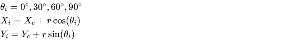
This will give you the precise coordinates for each hole on the arc.
Bolt Circle Distribution Pattern
Holes evenly distributed around a circle are known as a bolt circle pattern or pitch circle pattern. Figure 27-9 shows a typical bolt circle distribution pattern. This method is similar to the arc pattern, focusing on the circle’s center coordinates, radius or diameter, number of equally spaced holes, and each hole’s angle with the X-axis.
The programming approach involves selecting a starting position, usually the programming origin, and calculating coordinates for each hole. This ensures precise and consistent hole patterns.

Where (n) is the number of holes and (i) is the hole index (0 to (n-1)).
For example, a bolt circle with six holes and a radius of 5 inches:
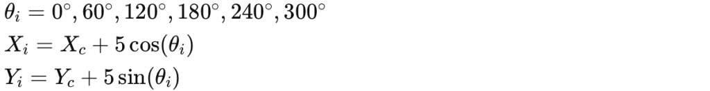
This will provide the coordinates for each hole on the circle, ensuring uniform distribution.
Summary
By mastering these various hole patterns in CNC machining, you can achieve precise, efficient, and consistent results in your projects. Understanding and implementing these patterns will enhance your programming skills and improve overall machining quality.