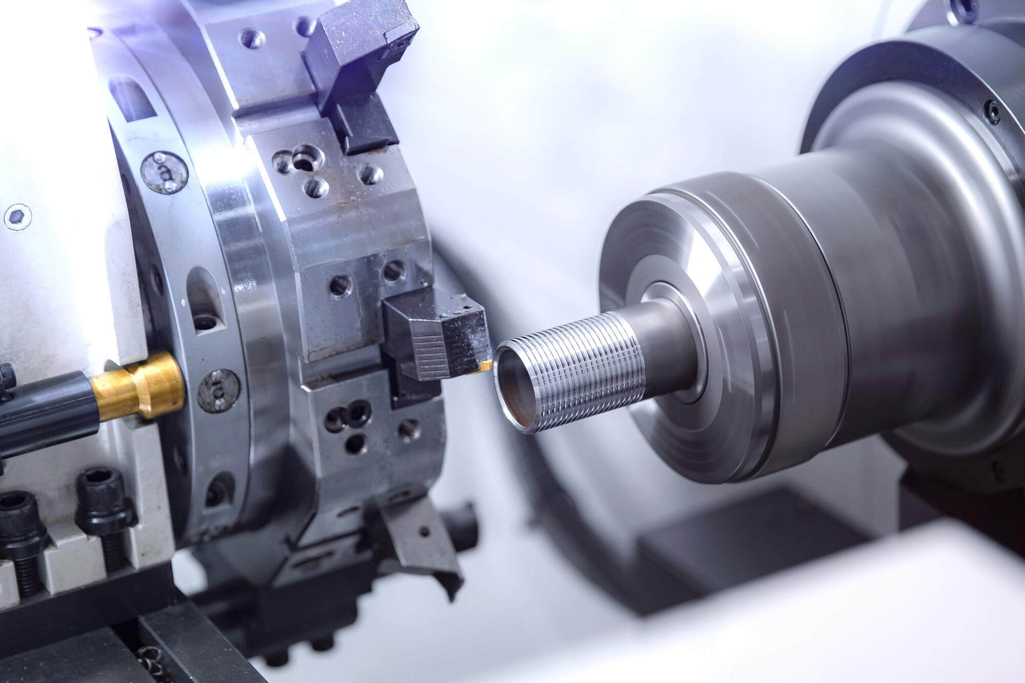
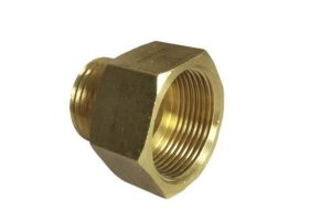
Thread turning is an essential process in machining, particularly in the realm of CNC (Computer Numerical Control) operations. It involves creating helical grooves on cylindrical or conical surfaces, essential for connecting parts without damage during assembly and disassembly. Threads are vital in various applications, such as fastening devices like screws and bolts, measuring tools like micrometers, motion transfer mechanisms like lead screws and camera lenses, and torque amplifiers like jacks.
The Basics of Thread Turning
In CNC lathes, thread turning stands out because it can achieve high-quality threads within a single setup. This capability is highly appealing to manufacturers, as it eliminates the need for additional clamping, reducing costs. The thread turning toolholder, equipped with replaceable inserts, is similar to other toolholders but features inserts designed for threading. These inserts must match the thread’s shape and size to be cut, typically featuring one, two, or three tips.
Types of Threads and Their Applications
The most common thread shape used in CNC programming is the 60° V-thread, available in both metric and imperial sizes. Other shapes include trapezoidal threads, square threads, and special threads used in various industries like aerospace and automotive. Threads can be cut on cylindrical or conical surfaces, internally or externally, and can be single or multi-start, left-handed or right-handed, and constant or variable pitch.
Programming Thread Turning on a CNC Lathe
Thread turning on a CNC lathe involves multiple passes, with each pass gradually increasing the thread depth. The process requires the spindle to be synchronized so that each pass starts at the same rotational position, ensuring consistent thread formation. Here’s a breakdown of the essential steps:
- Determining the Starting Position: Before the first pass, the tool must be positioned close to the workpiece, ensuring a safe and precise starting point.
- First Pass: The tool rapidly moves to the thread diameter and begins cutting the thread at the programmed feed rate, synchronized with the spindle rotation.
- Subsequent Passes: Each pass cuts deeper into the material, following the same path, until the final depth is achieved.
- Retraction: After each pass, the tool retracts rapidly to avoid damaging the newly cut thread.
- Final Pass: The last pass is usually a light cut to achieve the desired thread dimensions and surface finish.
Challenges in Thread Turning
One of the main challenges in thread turning is maintaining the synchronization between the tool and the spindle. Any deviation can result in a poor-quality thread. Additionally, the cutting tool must be set precisely perpendicular to the spindle axis to ensure the threads are cut correctly.
Practical Example
Consider a standard M10 x 1.5 metric thread with an outer diameter of 10mm and a pitch of 1.5mm. The process would involve the following steps:
- Setup: Load the correct tool insert for a 60° V-thread.
- Initial Positioning: Move the tool to a safe starting point, slightly away from the workpiece.
- First Pass: Rapidly move to the thread diameter and start the first pass, cutting into the material at a depth of around 0.2mm.
- Subsequent Passes: Continue cutting, each time increasing the depth incrementally by about 0.15mm until reaching the final depth of 0.866mm (using the formula for thread depth calculation: (0.866 \times \text{Pitch})).
- Final Pass: Make a light final pass to ensure a smooth finish.
Calculating Thread Depth and Passes
To calculate the thread depth and the number of passes needed, follow these steps:
Determine the Total Thread Depth: For a 60° V-thread, the thread depth (D) can be calculated using the formula:

For an M10 x 1.5 thread:

Calculate the Incremental Depth for Each Pass: The depth of each pass decreases as you get closer to the final thread depth. Start with a larger depth and gradually decrease. A common approach is to use a percentage of the remaining depth for each subsequent pass.
Incremental Depth Calculation Example
- First Pass: 0.2mm
- Second Pass: 0.15mm
- Third Pass: 0.12mm
- Fourth Pass: 0.10mm
- Fifth Pass: 0.08mm
- Sixth Pass: 0.05mm
- Seventh Pass: 0.03mm
- Eighth Pass: 0.02mm
The total depth after these passes should approximate the calculated thread depth, ensuring accurate and high-quality threading.
Advanced Thread Turning Techniques
Multi-Start Threads
Multi-start threads have two or more threads running parallel to each other. These are used to increase the lead distance without increasing the pitch. The programming for multi-start threads involves indexing the starting position for each thread.
Tapered Threads
Tapered threads are commonly used in applications requiring tight seals, such as in plumbing. The CNC programming for tapered threads involves changing the tool path to gradually decrease or increase the thread diameter.
Tips for Successful Thread Turning
- Tool Selection: Choose the correct insert for the thread type and material.
- Synchronization: Ensure the CNC machine maintains precise spindle synchronization.
- Incremental Depth: Use smaller depth increments to reduce tool load and improve thread quality.
- Coolant Use: Proper coolant application can extend tool life and improve the surface finish.
- Tool Setup: Ensure the threading tool is precisely perpendicular to the spindle axis to avoid tapering or inconsistent thread profiles.
Example: Detailed CNC Program for Thread Turning
Here is an example CNC program for turning a standard M10 x 1.5 thread:
O1000 (Thread Turning Example)
G21 (Metric Units)
G0 X12 Z2 (Position Tool to Starting Point)
G92 X10 Z-15 F1.5 (Set Threading Parameters)
N10 G0 X12
N20 G32 Z-15 F1.5
N30 G0 X12
N40 Z2
N50 X10.8
N60 G32 Z-15 F1.5
N70 G0 X12
N80 Z2
N90 X10.6
N100 G32 Z-15 F1.5
N110 G0 X12
N120 Z2
N130 X10.4
N140 G32 Z-15 F1.5
N150 G0 X12
N160 Z2
N170 X10.2
N180 G32 Z-15 F1.5
N190 G0 X12
N200 Z2
N210 X10.0
N220 G32 Z-15 F1.5
N230 G0 X12
N240 Z2
N250 X9.8
N260 G32 Z-15 F1.5
N270 G0 X12
N280 Z2
N290 X9.6
N300 G32 Z-15 F1.5
N310 G0 X12
N320 Z2
N330 X9.4
N340 G32 Z-15 F1.5
N350 G0 X12
N360 Z2
N370 X9.2
N380 G32 Z-15 F1.5
N390 G0 X12
N400 Z2
N410 X9.0
N420 G32 Z-15 F1.5
N430 G0 X12
N440 Z2
M30 (End of Program)
Mastering single-head thread turning on CNC lathes is a blend of precise programming, correct tool selection, and careful execution. With practice and attention to detail, achieving high-quality threads becomes a reliable and efficient process. Whether you’re producing screws, bolts, or other threaded components, understanding the nuances of thread turning will enhance your machining capabilities and product quality.
Other Articles You Might Enjoy
- Mastering Thread Tapping in CNC Machining Parts
Thread tapping is one of the most common hole machining operations on CNC machining centers, right after drilling. Due to its widespread application in many milling operations, most control systems…
- G32 Programming and Manual Threading in CNC Machining
When it comes to CNC machining, threading is one of those tasks where precision is paramount. Most of the time, the G76 threading cycle is the go-to for machinists, handling…
- Unlocking the Secrets of Thread Insertion in CNC Machining Parts
When it comes to CNC machining, thread insertion methods are crucial for ensuring high-quality results. Different approaches to thread insertion can significantly impact the efficiency, durability, and precision of the…
- Advanced Thread Turning Techniques: G76 Cycles in CNC Machining Parts
In the early days of CNC development, the G92 simple thread cutting cycle was a breakthrough in computer technology, providing an efficient method for thread turning. However, as technology advanced,…
- Detailed Analysis of Single-Point Boring Techniques in CNC Machining Parts
What is CNC Machining Boring CNC boring is an advanced machining process that uses computer numerical control (CNC) technology to enlarge or refine pre-existing holes in a workpiece with precision…
- The Basics of CNC Turning-Milling Compound Machining
The Basics of CNC Turning-Milling Compound Machining Programming The programming basics for CNC turning-milling compound machining can vary due to different CNC systems used in milling machines. These systems may…
- Diversity in CNC Machining Parts: From Standard Lathes to Multi-Axis Turning Centers
Walk into any machine shop, and you'll likely see a variety of lathes humming away. These versatile machines are the backbone of many manufacturing processes, especially when it comes to…


