Chapter 1: What is an STP File and Why It Matters in CNC
An STP file (also called STEP file, with extensions .stp or .step) is a common 3D file format used to transfer data between different CAD/CAM software. It’s like a universal translator that ensures your design can be opened, viewed, and edited across multiple software platforms.
So, why does the STP file format matter so much in CNC machining?
In my experience, customers often send designs in various formats, and STP files have consistently been the most trouble-free. CNC machines require G-code to run, and generating this code starts with importing a stable 3D model. If your file is faulty or incompatible, you’re stuck before you even begin.
I learned this the hard way years ago. A client sent a complicated mechanical part in a proprietary file format that our software couldn’t open properly. After several frustrating hours, we asked them for an STP file instead. Suddenly, things worked perfectly. Since then, I’ve trusted STP files as my go-to format for CNC projects.
Chapter 2: STP File Compatibility Across Major CAM Software: A Comparison Guide
The key to successful CNC machining often comes down to software compatibility. Not all CAM software handles STP files equally well. Let’s compare the most popular CAM software based on their compatibility with the STP file format:
| CAM Software | Direct STP Import | Import Speed | Ease of Use | Compatibility Issues | Recommended? |
|---|---|---|---|---|---|
| Fusion 360 | ✅ Yes | Fast | Easy | Few | Highly |
| Mastercam | ✅ Yes | Moderate | Medium | Occasional | Recommended |
| SolidCAM | ✅ Yes | Moderate | Medium | Minor | Recommended |
| HSMWorks | ✅ Yes | Fast | Easy | Few | Highly |
| BobCAD-CAM | ✅ Yes | Slow | Medium | Frequent | Limited |
| CAMWorks | ✅ Yes | Moderate | Medium | Minor | Recommended |
| GibbsCAM | ✅ Yes | Moderate | Medium | Occasional | Recommended |
My Experience
I’ve personally worked extensively with Fusion 360 and Mastercam. Fusion 360 imports STP files seamlessly, and it’s my favorite because of how intuitive and quick it is. Mastercam, on the other hand, is powerful but slightly less user-friendly when dealing with complex STP files. Occasionally, it misreads certain features or struggles with larger assemblies.
If speed and reliability are your top priority, Fusion 360 and HSMWorks are my top choices. For more specialized machining tasks, Mastercam or SolidCAM also handle most STP files quite well.
Chapter 3: How to Open and Use STP Files in Fusion 360, Mastercam, SolidWorks CAM, etc.
Opening an STP File
Opening an STP file is generally straightforward:
- Fusion 360:
- Open Fusion 360 and select “File” → “Open”.
- Select your STP file and click “Open”.
- The model imports quickly and is ready for toolpath creation.
- Mastercam:
- Click “File” → “Open”.
- Select the STP file from your directory.
- Adjust settings if needed (units, surfaces) and proceed.
- SolidWorks CAM / CAMWorks:
- Click “File” → “Open” and choose STP file.
- Confirm import settings (usually defaults are fine).
Real-Life Tips
When working with STP files, I recommend always checking model units upon import. A common mistake is importing inches as millimeters or vice versa. I’ve done this myself and wasted precious time fixing incorrect dimensions.
Best Practices Checklist:
- Verify units (inch/mm) before finalizing import.
- Check for surface errors (missing faces, edges).
- Ensure part orientation matches your machining setup.
Chapter 4: STP to G-code: Workflow Tips and File Preparation
The workflow from STP file to CNC machining typically looks like this:
- Import the STP file into your CAM software.
- Check geometry and dimensions for errors.
- Set your stock size, coordinate systems, and origins.
- Define machining operations (roughing, finishing, drilling).
- Generate toolpaths and simulate.
- Export toolpaths as G-code (.nc files).
Preparing the STP File for CNC Machining
I’ve noticed that STP files often need slight cleanup. For instance, unnecessary holes, threads, or chamfers might cause inefficient toolpaths. Removing or simplifying these features upfront saves time and reduces machine wear.
Table: Common File Preparation Steps
| Preparation Step | Why It Matters |
|---|---|
| Simplify complex geometries | Reduces machining time and cost |
| Remove small or unnecessary features | Prevents tool breakage or errors |
| Check and repair surfaces | Avoids machining errors or tool collisions |
| Set proper coordinate system | Ensures accurate machining positions |
| Verify file scale/units | Prevents costly machining errors |
| Confirm material thickness/stock | Optimizes stock use and machining paths |
Chapter 5: Fixing STP Import Issues: Conversion, Clean-up, and Best Practices
One frustration I’ve repeatedly faced is STP files that won’t import correctly. The most common issues include:
- Missing geometry or features.
- Corrupted surfaces or edges.
- Incorrect scaling or orientation.
How to Fix Common Issues
- Convert using another software: Sometimes I import troublesome files into SolidWorks or Fusion first, export them again as a new STP file, and re-import into Mastercam.
- Use online repair tools: Tools like CAD Exchanger or TransMagic often repair minor errors quickly.
- Check file source: Requesting a new export from the original CAD software (like SolidWorks or Inventor) can help.
I once struggled for hours trying to fix a corrupt STP file from a client. Eventually, re-exporting from SolidWorks solved the issue in minutes. Lesson learned: if you’re stuck, don’t hesitate to ask for a new file export.
Chapter 6: Bonus – Common Mistakes When Working with STP Files in CAM Environments
Working with STP files can seem straightforward, but even experienced machinists and engineers make avoidable mistakes that can lead to rework, machining errors, or even scrapped parts.
Let me walk you through the most common mistakes I’ve seen (and made myself), along with how to avoid them.
1. Assuming the STP file is “ready for machining”
Not all STP files are modeled with manufacturability in mind. Some are created by designers focused solely on product geometry—not how a CNC machine will cut it. I’ve seen beautifully modeled parts with impossible inside corners, overhangs that can’t be reached, and radii too small for any end mill to enter.
🔧 Tip: Always analyze the file from a machinist’s perspective. Can this geometry be cut with your available tools and axes?
2. Failing to verify units and scale
This one still bites teams regularly. If an STP file was created in metric and you’re working in inches (or vice versa), the scale can be completely wrong. I once milled a prototype that came out 10x smaller than expected… all because I forgot to check units on import.
🔧 Tip: Double-check dimensions and units immediately after import—don’t wait until after toolpathing!
3. Ignoring coordinate system and part orientation
An STP file often comes in with an arbitrary orientation. If you start programming without aligning the part to your machine’s axes, you’ll spend more time compensating than machining.
🔧 Tip: Align your coordinate system to match your vise, rotary, or fixture setup before defining any toolpaths.
4. Skipping over geometry cleanup
Even if the STP file opens cleanly, it might include duplicate surfaces, overlapping faces, or tiny fillets that can crash CAM simulations or confuse the postprocessor.
🔧 Tip: Use surface repair tools in your CAM software, or re-export the STP file after cleanup in SolidWorks/Fusion.
5. Overcomplicating toolpaths due to unnecessary details
Some files come loaded with cosmetic features that are irrelevant or unmachinable—like threads, logo engraving, or ultra-fine textures.
🔧 Tip: Simplify or suppress non-machinable details before generating toolpaths. Ask the client if those features are needed.
6. No simulation or collision check before export
Even if the STP file imported fine, you must always simulate your toolpaths. Skipping this step can lead to broken tools or gouged parts.
🔧 Tip: Run full simulations, especially for multi-axis or deep-pocketed parts. Visualize tool access and entry/exit moves.
Summary Table: Most Common STP File Mistakes
| Mistake | Impact | How to Avoid |
|---|---|---|
| Wrong units or scale | Oversized or undersized part | Confirm units on import and compare key dims |
| Poor part orientation | Machining inefficiencies | Align coordinate system before toolpathing |
| Geometry too complex to machine | Broken tools or time waste | Suppress cosmetic or unmachinable features |
| Using STP file “as-is” | Wasted setup or scrap | Always review for machinability |
| No simulation | Crash risk | Always simulate toolpaths |
| Relying on one software only | Import errors or crashes | Cross-check in Fusion, SolidWorks, or repair tools |
Chapter 7: Case Study – From STP Upload to Finished CNC Part
7.1 Introduction: Why a Case Study?
Sometimes the best way to understand the real value of an STP file is to walk through a real-world job from beginning to end. I’ve handled dozens of parts based on STP files, but one recent project sticks out as a perfect example of how important compatibility, file quality, and workflow discipline really are.
This wasn’t a glamorous aerospace part or a high-precision mold cavity. It was a structural bracket for an industrial machine—fairly simple looking, but with just enough detail to be dangerous if we rushed.
7.2 The Project Brief
The customer emailed us a .stp file of a support bracket. It was a medium-sized aluminum part (about 250 x 120 x 30 mm), intended for a CNC-milled prototype. Timeline was tight—they needed it machined, anodized, and shipped in under 4 business days.
Key details:
- File format:
part_3409_support.stp - Material: 6061-T6
- Tolerances: ±0.05 mm general, ±0.01 mm for mounting holes
- Delivery: within 96 hours
7.3 Step 1 – Opening and Checking the STP File
We first opened the STP file in Fusion 360. Thankfully, it loaded cleanly—no missing surfaces or scaling issues.
But there were a few red flags:
- The coordinate system was misaligned (part was tilted 45° off X/Y plane)
- Threads were modeled as helical cuts, which is unnecessary for CNC
- A few tiny embossed text features that didn’t affect function but would affect milling time
Action Taken:
- Re-oriented the part flat to the XY plane
- Suppressed the threads and replaced them with tapped hole annotations
- Removed cosmetic text using surface-edit tools
- Re-exported a clean version of the STP file to use in CAM
7.4 Step 2 – Importing into CAM and Generating Toolpaths
We opened the cleaned STP file in Mastercam and quickly realized we’d saved ourselves a lot of time by cleaning it up in Fusion first.
Toolpath Strategy:
- Face milling
- Contour milling for profile
- Pocketing for cutouts
- Drilling + tapping for M5 holes
- Fillet tool for rounded edges
We ran a quick simulation and confirmed:
- Tool reach was adequate
- No collisions
- No overcuts due to misinterpreted geometry
⏱️ Time spent in CAM: ~45 minutes
7.5 Step 3 – Machining and Inspection
We machined the part on our 3-axis vertical mill using:
- 10 mm end mill (roughing)
- 6 mm ball end mill (fillets)
- 4.2 mm drill + M5 tap for holes
The CNC machine didn’t throw any alarms, which is always a relief. The STP-based G-code ran clean. Once the part came off the mill, we checked the following:
| Feature | Tolerance Specified | Measured Result | Within Tolerance |
|---|---|---|---|
| Overall length | ±0.05 mm | 249.96 mm | ✅ |
| Hole pitch (center) | ±0.01 mm | 119.99 mm | ✅ |
| Cutout depth | ±0.05 mm | 15.02 mm | ✅ |
| Surface finish (Ra) | N/A | 1.8 μm | ✅ (visual OK) |
7.6 Step 4 – Post-Machining Adjustments and Anodizing
The part was deburred, cleaned, and sent for black anodizing. Anodizing thickness was 10μm, which we had accounted for in hole clearances.
After finish and packing, the part shipped out on time—actually a day early. The client replied with a thank-you email and has since sent three more STP files for similar components.
7.7 Lessons Learned from This Case
What went well:
- STP file compatibility: Fusion and Mastercam handled it without errors
- Early cleanup: Avoided surprises during CAM setup
- Simulation & toolpath planning: Prevented issues that could’ve delayed delivery
What could have gone wrong:
- If we hadn’t reoriented the coordinate system, setup would’ve taken longer
- If we had left the thread features in, we may have broken a tool
- If we hadn’t double-checked tolerances in the STP file, hole misalignment might have happened
7.8 STP File Case Study Summary Table
| Step | What We Did | Why It Mattered |
|---|---|---|
| File review | Opened and cleaned STP in Fusion 360 | Ensured geometry was machinable and efficient |
| CAM setup | Imported into Mastercam and created toolpaths | Smooth G-code generation |
| CNC machining | Used standard tools and verified during roughing phase | Minimized downtime and tool changes |
| Inspection | Verified dimensions with CMM and calipers | Confirmed compliance with tolerances |
| Finish + delivery | Sent for anodizing, packed, and shipped ahead of schedule | On-time delivery = happy client |
7.9 Why This Case Proves the Value of STP File Compatibility
This job could’ve been delayed or failed outright if the STP file had been incompatible, poorly modeled, or required reverse engineering. Instead, because we had:
- A clean, usable STP file
- CAM software that handled it well
- A tested workflow
…we were able to go from STP file to finished part in under 3 days.
That’s the power of good preparation and STP file compatibility in real CNC environments.
Chapter 8: Final Summary & Software Recommendation
8.1 Why STP File Compatibility Is a Game-Changer
After working with hundreds of CNC jobs, one lesson is clear: a clean, compatible STP file can either streamline your entire process—or break it before it begins.
Whether it’s importing, simulation, quoting, or toolpath generation, everything depends on whether your CAM software handles the STP file properly. A good STP workflow cuts down lead time, reduces communication issues, and gives your CNC team more confidence on the shop floor.
8.2 Key Takeaways from This Guide
Let’s recap the most important insights we’ve covered in this guide:
| Insight | Why It Matters |
|---|---|
| STP files are the universal 3D format | Works across CAD/CAM systems, ideal for CNC collaboration |
| Not all CAM software handles them equally | Some systems import faster and with fewer errors than others |
| Cleaning up the STP file is essential | Speeds up CAM setup, prevents geometry problems |
| Always verify scale and orientation | One of the most common sources of toolpath mistakes |
| Simulation is not optional | Even if the STP file imports fine, only simulation ensures safe cutting |
| Software compatibility saves time | If your CAM tool understands STP natively, you skip hours of conversion steps |
8.3 Our CAM Software Recommendations
Based on experience, feedback from peers, and repeatable results, here’s how I’d rank major CAM software by STP file compatibility and ease of use:
| Rank | CAM Software | Strengths |
|---|---|---|
| 1 | Fusion 360 | Fast import, great repair tools, cloud-based sharing |
| 2 | HSMWorks | Easy SolidWorks integration, reliable STP workflow |
| 3 | SolidCAM | Powerful for complex parts, solid STP import |
| 4 | Mastercam | Versatile, but needs more prep work for complex STP files |
| 5 | CAMWorks | Solid integration, especially for feature-based machining |
| 6 | GibbsCAM | Decent compatibility, but more learning curve |
| 7 | BobCAD-CAM | Budget-friendly, but STP import can be hit-or-miss |
If you work with a lot of customer-supplied STP files, I strongly recommend Fusion 360 or HSMWorks. Their workflows are smooth, intuitive, and less prone to crashing on large models.
8.4 Final Word
Don’t underestimate how much a single STP file can impact your CNC workflow. Incompatible files, broken geometry, or messy units cost time and money. Choosing the right CAM software—and setting up a smart, consistent STP file process—can give your team an edge that scales with every project.
If I had to summarize the takeaway in one sentence:
“A good STP file and the right CAM software can turn a 4-day job into a 2-day win.”
FAQ
To wrap things up, here’s a frequently asked questions (FAQ) section to address real concerns from users trying to work with STP files in CAM environments:
1. Can I use STP files for CNC machining directly?
Yes, but only after importing into CAM software that supports toolpath creation. You’ll need to generate G-code after defining operations.
2. Why won’t my STP file open in Mastercam?
It might be corrupted, too large, or use unsupported geometry. Try importing into Fusion 360 or SolidWorks first and re-exporting.
3. Which software supports STP files best?
Fusion 360, HSMWorks, and SolidCAM are excellent with STP files. Fusion is especially fast and user-friendly.
4. Can I edit STP files directly?
Not really. STP is a neutral exchange format, not intended for full parametric editing. You can adjust faces or delete features but not edit sketches or design history.
5. Why do imported STP files have missing surfaces?
Sometimes the export process from the original CAD software was incomplete or the surfaces were too complex. Use “repair geometry” tools or re-export.
6. Is an STP file better than STL for CNC?
Absolutely. STL files are mesh-based and often lack precision. STP files preserve true geometry and are far better suited for CNC.
7. Can I use free software to view STP files?
Yes. Free tools like FreeCAD, eDrawings Viewer, and Autodesk Viewer let you open and inspect STP files without licenses.
8. What’s the best way to extract dimensions from an STP file?
Open the STP file in Fusion 360 or SolidWorks, and use the measure tool on faces, edges, or holes.
9. Can I convert an STP file to G-code without CAM software?
Not directly. You need CAM software to interpret the 3D model and create toolpaths before exporting G-code.
10. Why do threads or holes disappear in my imported STP file?
STP files may not include cosmetic or cosmetic-thread info. Threads often require manual modeling or feature recognition in CAM.
11. Are STP files safe to send to external vendors?
Yes. STP files don’t contain design history or IP-sensitive data like some native formats. They’re ideal for sharing with manufacturers.
12. Can I use STP files for 5-axis machining?
Yes, as long as your CAM software supports multi-axis strategies. Toolpath planning is critical—orientation and tool access matter.
13. How big is a typical STP file?
It depends on complexity. Simple parts might be 1–5MB. Complex assemblies or detailed parts could be 20MB or more.
14. Can I check wall thickness or undercuts in an STP file?
Yes, but you’ll need CAM software with analysis tools—or use a CAD viewer with section and measurement capability.
15. What’s the easiest way to clean up a messy STP file?
Open it in Fusion 360 or SolidWorks, delete unnecessary features, simplify geometry, and re-export a cleaner STP file.
External Reference Links
To help you go further with this topic, I’ve compiled a few reliable, non-commercial, knowledge-based sources. These are great for technical reference, education, or troubleshooting deeper issues with STP files in CAM environments.
Authoritative Knowledge Resources
| Source | Description | Direct Link |
|---|---|---|
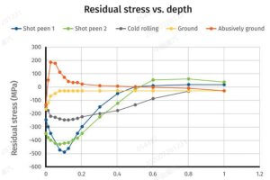
| TWI – Stress Relief FAQ | Covers file integrity and stress in parts, useful for STP-based machined components | TWI Link |
| Wikipedia – STP File | Detailed overview of STEP format (.stp), standards, and compatibility notes | Wikipedia STP |
| Wikipedia – CAM Software | List of CAM software and features, including STP compatibility | Wikipedia CAM |
Bonus: Free STP Viewers and Online Tools
If you’re just starting out or need to preview STP files without a license:
- Autodesk Viewer: viewer.autodesk.com
- FreeCAD: freecad.org
- eDrawings Viewer: edrawingsviewer.com
- Onshape (cloud CAD): onshape.com
- CAD Format Converter: CAD Format Converter
Other Articles You Might Enjoy
- How to Use a DXF File for CNC: From Design to Toolpath
Introduction I remember the first time I used a DXF file for my CNC router. I had a design in my head, scribbled it out on a piece of paper, then realized…
- Prototype CNC Machining: Everything You Need to Know
The emergence of CNC machining has changed the entire manufacturing industry. This technology has been developed for more than 70 years and is now very mature. And used in various…
- Mastering GD&T Symbols for CNC Machining: A Practical Guide for Engineers
Introduction Overview of GD&T Symbols and CNC Geometric Dimensioning and Tolerancing (GD&T) is a language used to define the geometry and tolerance of mechanical components. When working with CNC (Computer Numerical…
- Mastering stl to gcode: A Complete Guide for 3D Printing and CNC Enthusiasts
Chapter 1. Introduction I remember the first time I tried converting stl to gcode for a simple 3D printing project.I thought it would be as straightforward as clicking a button.But…
- Top 5 Techniques for Prototype Manufacturing: CNC Machining, 3D Printing, and More
Introduction: What Is Prototype Manufacturing and Why Is It Important? When I first encountered the term “prototype manufacturing,” I realized it was a turning point in how products come to…