Chapter 1: Introduction
Chamfering is one of the most essential finishing operations in precision manufacturing. Over my many years working in CNC machining, I’ve discovered that a well-executed chamfer does more than just smooth out a sharp edge—it can dramatically enhance a part’s performance, assembly ease, and even safety. Custom Machining techniques allow us to tailor the chamfering process to meet specific design requirements, ensuring optimal results for each unique component. In this chapter, I’ll introduce what chamfering is, why it’s so important in modern manufacturing, and share some personal insights from my field experience. Our facility consistently produces high-quality CNC machined parts that exemplify the precision and efficiency of today’s manufacturing technology.
1.1 What Is Chamfering?
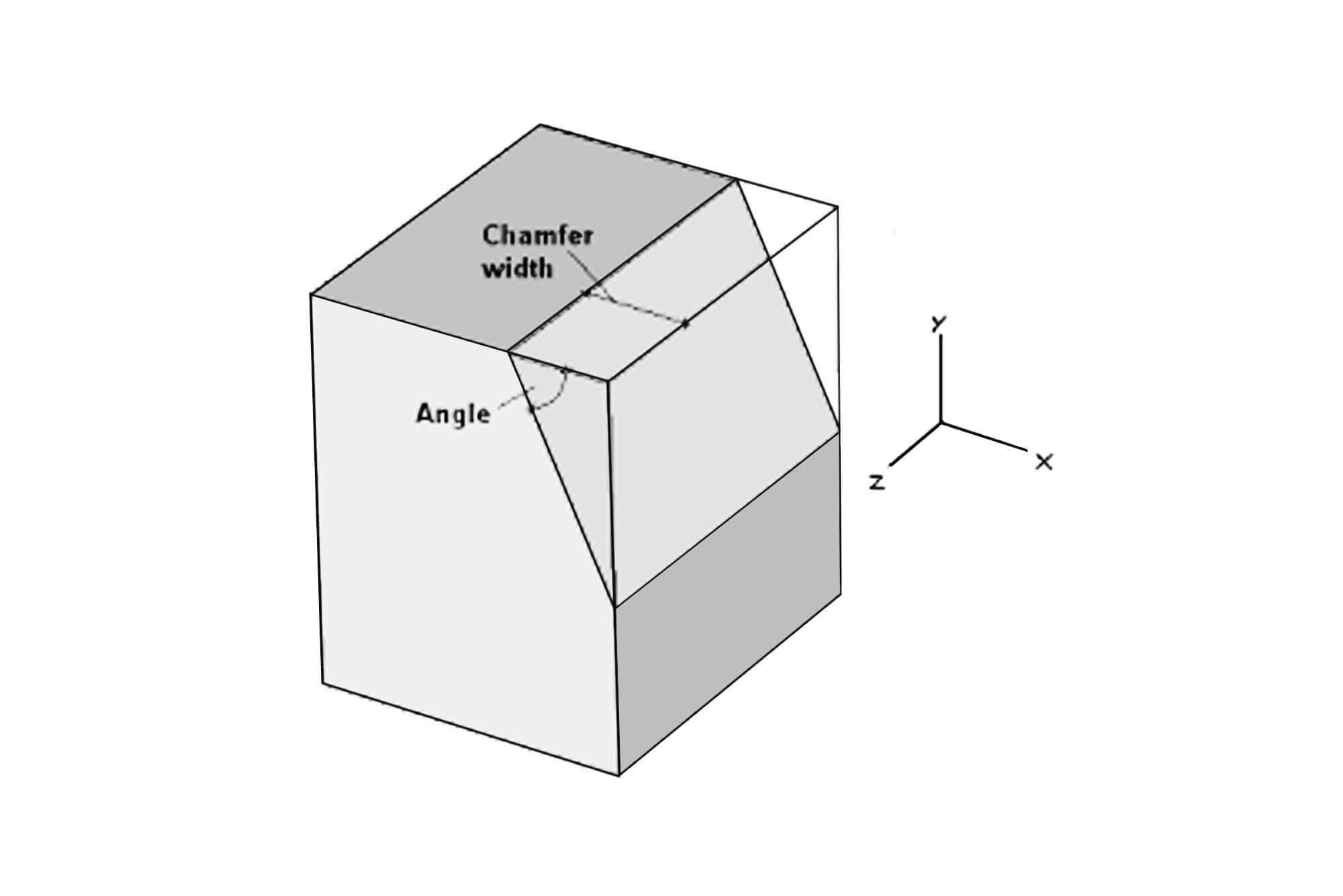
Chamfering involves cutting or beveling the sharp edge of a workpiece to create an angled surface. Unlike filleting, which creates a rounded transition, chamfering produces a flat, sloping edge. This technique is used to eliminate sharp corners that can cause stress concentrations, reduce the risk of damage or injury, and improve both the functionality and aesthetics of the final product.
In many industries—from aerospace and automotive to medical devices and furniture manufacturing—a chamfered edge is critical. For example, in high-stress applications, a chamfer helps distribute loads more evenly, reducing the chance of crack initiation. In assembly processes, chamfered edges allow parts to mate more seamlessly, improving overall fit and reducing assembly time.
1.2 The Importance of Chamfering in CNC Machining
Before the advent of CNC machining, chamfering was often performed manually or using semi-automated methods, which sometimes resulted in inconsistent quality. Today, CNC machining has revolutionized chamfering by delivering extreme precision and repeatability. I remember early in my career when a client needed thousands of parts with a specific 45° chamfer. Manual methods led to variations that were unacceptable for high-performance applications. Switching to CNC machining not only solved the consistency issue but also reduced lead times and material waste.
Why is chamfering so important?
- Stress Reduction: A chamfered edge minimizes stress concentrations that can lead to material failure.
- Assembly Enhancement: Chamfered parts are easier to align and assemble, reducing the risk of misalignment and damage during assembly.
- Aesthetic Improvement: In consumer products and visible components, a chamfer adds a refined finish that enhances the overall appearance.
CNC machining offers the ability to program precise chamfer angles, depths, and profiles. With modern CNC systems, even intricate chamfer operations can be performed consistently across high volumes of production. The digital control enables a repeatable process that is critical for meeting the tight tolerances required in today’s advanced manufacturing environments.
1.3 My Personal Experience with Chamfering
I vividly remember a project where we needed to manufacture chamfered components for a high-performance aerospace application. The design specification required a 45° chamfer on every edge with a tolerance of ±0.01 mm. Initially, our manual processes couldn’t guarantee the consistency needed, and we encountered a high rate of rejects. When we transitioned to a fully CNC-controlled process, we were able to program the exact chamfer parameters and achieve uniformity across all parts. This shift not only enhanced the performance of the components under extreme operating conditions but also cut down on rework and scrap, saving the client both time and money.
In another project involving automotive parts, I used CNC machining to produce chamfered edges on aluminum components. The process improved the assembly by ensuring the parts fit together seamlessly, which in turn reduced vibration and wear in the final vehicle assembly. These experiences have made it clear to me that precision chamfering is not a luxury but a necessity in high-end manufacturing.
1.4 Industry Relevance
Industries that rely on precision components—such as aerospace, automotive, heavy machinery, and medical devices—place high importance on chamfering. When professionals search for “chamfer” in the context of CNC machining, they’re often looking for:
- Techniques to achieve consistent chamfer dimensions.
- Guidance on programming and tooling for chamfer operations.
- Tips to avoid common errors like overcutting or uneven chamfers.
- Case studies and real-world examples that validate the benefits of CNC machining.
This guide is designed to meet those needs, providing not only technical details but also personal insights and practical examples from the field. As I share my experiences and deep dive into the methods, tools, and parameters used in CNC chamfering, I aim to help professionals enhance their own machining processes and achieve superior results.
Chapter 2: Chamfering Methods in CNC Machining
In CNC machining, there is no one-size-fits-all solution for chamfering. Over the years, I have experimented with several methods to achieve the best chamfer quality for different materials and geometries. This chapter explores the various techniques available for chamfering, comparing their benefits, limitations, and typical applications.
2.1 Overview of Chamfering Techniques
Chamfering can be performed using multiple CNC methods. Each method offers distinct advantages, depending on the workpiece geometry and material. Here are the primary techniques I have used:
2.1.1 Using Chamfer Mills
Chamfer mills are dedicated tools designed specifically to create a beveled edge. These tools are available in several angles (commonly 30°, 45°, 60°) and are ideal for producing consistent chamfers along linear edges.
- Advantages:
- Consistency: Chamfer mills deliver uniform chamfers every time.
- Ease of Programming: They require minimal adjustments and are straightforward to set up.
- Speed: Ideal for high-volume production with consistent geometry.
- Limitations:
- Limited to Straight Edges: They are best suited for flat, linear edges and may not handle complex curves well.
- Tool Wear: Frequent use on hard materials can lead to significant wear if not properly maintained.
In one automotive project, I used chamfer mills to create a 45° chamfer on metal panels. The process was simple, and the results were extremely consistent—each edge met the design specifications without any need for manual touch-ups.
2.1.2 Using End Mills for Chamfering
Standard end mills can also be programmed to create chamfers, though they are not dedicated for that purpose. This method is particularly useful when the workpiece has a complex or curved edge that requires a more flexible approach.
- Advantages:
- Versatility: End mills can perform multiple operations, including chamfering, contouring, and profiling.
- Cost-Effective: Often, the same end mill can be used for various operations, reducing tooling costs.
- Limitations:
- Programming Complexity: Achieving a uniform chamfer requires meticulous programming of the tool path.
- Inconsistency Risk: Without careful control, chamfers produced by end mills may vary along the workpiece.
I once worked on a project for a medical device where the component required a complex edge profile. We opted for using an end mill to perform chamfering. Although it required a sophisticated program and several iterations to perfect the process, the flexibility of the end mill allowed us to achieve a custom chamfer profile that met our stringent quality requirements.
2.1.3 CNC Turning for Chamfering
For cylindrical parts, CNC turning offers an integrated solution for chamfering. On a CNC lathe, chamfering can be performed as part of the turning cycle, creating beveled edges on the end faces or along the cylindrical surface.
- Advantages:
- Integration: Chamfering is integrated into the turning process, reducing the need for secondary operations.
- High Precision: CNC turning provides tight tolerances and uniform chamfering across all parts.
- Efficiency: Since chamfering is performed during turning, it saves time and streamlines the workflow.
- Limitations:
- Limited to Rotational Parts: This method is mainly applicable to cylindrical or rotational components.
- Tooling Requirements: Specialized turning tools are required, and setup must be precise to avoid errors.
I have used CNC turning extensively when machining hub bearings and shafts. By integrating chamfering into the turning process, we achieved the necessary bevel with minimal additional setup time. This method proved especially effective for high-volume production where consistency is critical.
2.1.4 Specialized Chamfering Tools on Multi-Axis CNC Machines
For parts that require compound or non-linear chamfers, specialized chamfering tools mounted on multi-axis CNC machines offer a robust solution. These tools can handle complex geometries that standard tools cannot, enabling the creation of unique edge profiles in one setup.
- Advantages:
- Complex Geometry: Capable of machining curved and compound chamfers that are otherwise difficult to achieve.
- Superior Finish: Produces very smooth edges with excellent surface quality.
- Flexibility: Multi-axis machines allow simultaneous machining of multiple surfaces, saving time.
- Limitations:
- Higher Cost: Specialized tools and multi-axis machines come with a higher price tag.
- Programming Complexity: Requires advanced programming and operator expertise.
In one high-end aerospace project, we needed to produce a compound chamfer on an irregularly shaped component. Using a 5-axis CNC machine with a specialized chamfering tool, we were able to achieve a flawless edge that met all the tight design specifications. Although programming was challenging, the final product demonstrated exceptional quality and precision.
2.2 When to Choose Chamfering Versus Filleting
A frequent question I encounter is when to use chamfering versus filleting. While both processes smooth out sharp edges, their applications differ:
- Chamfering creates a flat, angled edge, which is ideal for reducing stress concentrations and facilitating assembly in applications where precise edge geometry is required. It is typically used when a part needs to fit together with minimal clearance issues.
- Filleting, on the other hand, produces a rounded edge. This is often used in applications where aesthetics or ergonomic considerations are paramount. Fillets are common in consumer products, medical devices, and parts where a softer transition is desired.
In my work, I’ve chosen chamfering when the goal is to ensure tight assembly tolerances and reduce the risk of stress concentration, particularly in metal parts used in high-performance applications.
2.3 Data Table: Comparison of Chamfering Methods
Below is a detailed table comparing the various chamfering methods I’ve used in CNC machining. This table is based on years of practical experience and research, offering a quick reference for choosing the right technique.
| Method | Best For | Advantages | Disadvantages | Typical Applications | Tool Examples | Additional Notes |
|---|---|---|---|---|---|---|
| Chamfer Mills | Straight edges | High consistency, ease of programming | Limited to linear edges; tool wear may be high | Automotive panels, flat metal parts | Standard chamfer mill cutters | Ideal for 30° to 60° chamfers |
| End Mills | Complex, curved edges | Versatile; cost-effective for multiple operations | Requires precise programming; risk of inconsistency | Custom medical devices, precision components | Carbide end mills | Can serve dual purposes in contouring and chamfering |
| CNC Turning | Cylindrical parts | Integrated with turning; high precision | Limited to rotational parts; specialized tools needed | Hub bearings, shafts, rollers | CNC turning chamfer tools | Combines chamfering with overall turning cycle |
| Specialized Chamfering Tools on Multi-Axis Machines | Compound/challenging geometries | Excellent for complex chamfer profiles; superior finish | High cost; advanced programming required | Aerospace components, custom molds | Custom-designed multi-axis chamfer tools | Requires expert programming and machine capability |
2.4 Personal Reflections on Chamfering Methods
Throughout my career, I have experimented with different chamfering methods on CNC machines. One memorable automotive project required a precise 45° chamfer on all edges of a critical component. Initially, we attempted the process with standard end mills; however, the results were inconsistent, leading to frequent rework. After switching to a dedicated chamfer mill, the uniformity and surface finish improved dramatically. This experience underscored the importance of selecting the right tool for the job.
I also recall a challenging aerospace application where the part featured compound chamfers on both flat and curved surfaces. Using a 5-axis CNC machine with specialized chamfering tools, we were able to achieve an intricate chamfer profile that met strict design requirements. Although programming the multi-axis tool path was complex, the outcome was a flawless edge that contributed to the part’s overall performance and safety.
These personal experiences have taught me that the method chosen for chamfering directly affects not only the quality of the edge but also the efficiency of the overall production process. With proper planning, tool selection, and parameter optimization, CNC machining can deliver exceptional results in even the most demanding applications.
Chapter 3: CNC Chamfering Tools and Parameters
CNC machining has redefined precision manufacturing, and chamfering is no exception. Over the years, I have learned that selecting the right tools and optimizing machining parameters are critical to achieving high-quality chamfers. In this chapter, I will delve into the various tools used for chamfering, explain the importance of key CNC parameters, provide detailed data tables, and share personal insights from the field.
3.1 Choosing the Right Tools for Chamfering
Selecting the correct tool is the foundation of a successful chamfering operation. In my experience, using the proper tool not only enhances edge quality but also reduces tool wear and ensures consistent production, particularly when working with high-precision requirements.
3.1.1 Types of Chamfering Tools
There are several types of tools available for creating chamfers in CNC machining. Each tool has its own advantages and is best suited for specific applications:
- Chamfer Mills:
These tools are purpose-designed for chamfering. Chamfer mills typically have a cutting head angled at common values such as 30°, 45°, or 60°. I have used chamfer mills for parts that require a uniform, straight-edge bevel. Their ease of programming and setup makes them ideal for high-volume production, especially in automotive or aerospace applications where every edge must be consistent. - End Mills:
Standard end mills can also be used for chamfering if the CNC program is carefully designed. The advantage here is versatility; an end mill can perform multiple operations on the same workpiece. In one instance on a medical device project, we programmed an end mill to produce a gentle chamfer on a curved edge. While the process required precise control, the flexibility of the end mill allowed us to achieve a custom edge profile not possible with a dedicated chamfer mill. - Specialized Chamfering Tools:
For more intricate chamfering tasks—especially on parts with compound or non-linear edges—specialized chamfering tools come into play. These tools are often used on multi-axis CNC machines, enabling us to produce complex chamfer profiles in a single setup. Although they may be more expensive, I have found that in applications such as high-end aerospace components, the investment is justified by the superior quality of the finished edge. - CNC Lathe Chamfering Tools:
When working on cylindrical parts, particularly in turning operations, chamfering tools integrated into CNC lathes offer a cost-effective and precise solution. Using specialized turning tools, we can produce chamfers on the ends or along the periphery of shafts and hub bearings. This integration not only reduces additional setups but also ensures that chamfering is part of the same cycle as turning, enhancing overall efficiency.
3.1.2 Factors to Consider in Tool Selection
In my day-to-day work, I always evaluate a few critical factors when choosing a chamfering tool:
- Material Compatibility:
Different workpiece materials (e.g., aluminum, steel, titanium, ceramics) require different tools. For example, machining hardened steel or titanium often demands tools with carbide or diamond-like coatings. The selected tool must not only cut efficiently but also withstand the material’s abrasiveness without excessive wear. - Chamfer Angle Requirements:
The design specifications of a part dictate the chamfer angle. If the part requires a 45° chamfer, the tool must be capable of maintaining that angle consistently. I often rely on tools that come pre-angled or on adjustable tool holders that allow fine tuning of the cutting angle. - Tool Geometry and Size:
The shape and size of the tool influence the chamfer’s final quality. A tool with a larger diameter might remove material more efficiently, while a smaller tool might be needed for delicate or intricate edges. Balancing these factors is crucial to achieving the desired edge finish without compromising efficiency. - Durability and Cost:
While high-end, specialized chamfering tools can be more expensive, their durability often justifies the investment in high-volume or high-precision applications. I have observed that using quality tools reduces overall production costs by minimizing tool changes and scrap rates.
3.2 Key CNC Machining Parameters for Chamfering
In addition to tool selection, the machining parameters you set—such as feed rate, spindle speed, and depth of cut—have a profound impact on chamfer quality. Optimizing these parameters is essential for achieving a consistent, smooth chamfer with minimal errors.
3.2.1 Feed Rate
The feed rate determines how fast the tool moves along the workpiece. In chamfering, it directly affects:
- Cutting Forces:
A lower feed rate minimizes cutting forces, reducing the risk of tool deflection and ensuring a smoother cut. - Surface Finish:
An optimal feed rate results in a fine surface finish. If the feed rate is too high, it can lead to a rough, uneven chamfer. - Tool Life:
Consistently optimized feed rates help prolong tool life by reducing excessive wear and overheating.
From my experience, starting with a conservative feed rate and gradually increasing it based on test cuts is the best practice. This method allows you to fine-tune the feed until the chamfer quality meets the desired standard.
3.2.2 Spindle Speed
Spindle speed plays a crucial role in controlling the cutting process. The optimal spindle speed depends on several factors:
- Material Hardness:
Harder materials like stainless steel or titanium require lower spindle speeds to prevent excessive heat buildup and tool wear. - Tool Material:
Tools made from advanced materials like carbide or those with special coatings can often handle higher speeds. - Desired Surface Finish:
A higher spindle speed, when matched with the correct feed rate, can produce a smoother chamfer. However, too high a speed might cause chatter, compromising the finish.
In one of my projects with aluminum, a higher spindle speed paired with a moderate feed rate produced a remarkably smooth chamfer. Balancing these factors is critical to achieving the ideal surface finish and ensuring repeatability.
3.2.3 Depth of Cut
The depth of cut is the amount of material removed in a single pass. For chamfering, this parameter is especially sensitive:
- Shallow Depths:
Typically, chamfering is done in several shallow passes rather than a single deep cut. This gradual approach minimizes tool stress and helps maintain a uniform chamfer. - Incremental Cutting:
Breaking the process into multiple passes allows for better control of material removal and ensures that the chamfer remains consistent along the entire edge.
In my experience, using a multi-pass strategy often results in a smoother edge with better dimensional accuracy. It may take slightly longer, but the improvement in quality justifies the extra time.
3.3 Common Mistakes in CNC Chamfering and How to Avoid Them
Even with proper tool selection and optimized parameters, mistakes can occur. I’ve encountered several common issues over the years and have learned effective strategies to address them.
3.3.1 Overcutting or Undercutting
- Issue:
A chamfer that is too deep (overcut) or too shallow (undercut) can lead to poor assembly fit or uneven stress distribution. - Causes:
This typically results from incorrect depth-of-cut settings or an unbalanced feed rate. - Solution:
I always recommend conducting trial runs on scrap material. Adjust the depth of cut incrementally and monitor the chamfer until the desired dimension is achieved.
3.3.2 Uneven Chamfer Edges
- Issue:
Variations in the chamfer angle along the edge can compromise both aesthetics and function. - Causes:
Common causes include tool deflection, misalignment of the workpiece, and programming errors. - Solution:
Ensuring that the workpiece is securely fixtured is crucial. Additionally, using dedicated chamfering tools instead of generic end mills, and verifying the tool path through CAM simulation, can prevent such inconsistencies.
3.3.3 Excessive Tool Wear
- Issue:
Rapid tool wear can lead to rough surfaces and inconsistent chamfers. - Causes:
High spindle speeds, improper feed rates, and inadequate coolant application are typical culprits. - Solution:
I always choose tools with the appropriate coatings and ensure proper coolant usage. Regular tool inspections and scheduled maintenance can significantly reduce wear-related issues.
3.3.4 Programming Errors
- Issue:
Inaccurate G-code programming can cause unwanted deviations in the chamfer profile. - Causes:
Errors may stem from miscalculations, failure to simulate the tool path, or neglecting to account for tool compensation. - Solution:
I make it a standard practice to simulate the machining process using CAM software before running the actual program. This allows me to catch errors early and make necessary adjustments.
3.4 Data Table: Comparison of CNC Chamfering Parameters
Below is a comprehensive table summarizing recommended CNC chamfering parameters for various materials based on my field experience:
| Material | Tool Type | Feed Rate (in/min) | Spindle Speed (RPM) | Depth of Cut (in) | Chamfer Angle (°) | Notes |
|---|---|---|---|---|---|---|
| Aluminum | Chamfer Mill | 50 – 70 | 10,000 – 12,000 | 0.005 – 0.010 | 45 | High speed yields smooth finish |
| Mild Steel | End Mill | 30 – 40 | 8,000 – 10,000 | 0.003 – 0.007 | 45 | Lower speeds prevent overheating |
| Stainless Steel | Chamfer Mill | 20 – 30 | 6,000 – 8,000 | 0.002 – 0.005 | 45 | Use coated tools to reduce friction |
| Titanium Alloy | Specialized Chamfer Tool | 15 – 25 | 5,000 – 7,000 | 0.001 – 0.003 | 30 | Conservative parameters to prevent tool wear |
| Carbon Fiber Composite | End Mill | 40 – 60 | 9,000 – 11,000 | 0.004 – 0.008 | 45 | Adjust to avoid material delamination |
| High-Strength Alloy | Chamfer Mill | 25 – 35 | 7,000 – 9,000 | 0.003 – 0.006 | 60 | Requires careful coolant management |
3.5 Data Table: Common CNC Chamfering Errors and Remedies
Here’s another table summarizing common issues encountered during chamfering, their causes, and recommended solutions:
| Issue | Description | Likely Cause | Recommended Remedy | Impact on Quality |
|---|---|---|---|---|
| Overcutting | Chamfer depth is greater than specified | Excessive depth per pass, high feed rate | Reduce depth incrementally; adjust feed rate | May weaken edge; affects part fit |
| Undercutting | Chamfer depth is insufficient | Insufficient depth setting | Increase depth incrementally | Results in sharp, unmodified edges |
| Uneven Chamfers | Inconsistent chamfer profile along the edge | Tool deflection, misalignment | Secure workpiece firmly; recalibrate tool offset | Leads to poor assembly and stress points |
| Tool Wear/Chatter | Rough, inconsistent edge finish | High spindle speed, insufficient coolant | Use coated tools; optimize coolant flow; reduce speed | Deteriorates surface finish; increases scrap |
| Programming Errors | Chamfer dimensions deviate from design | Incorrect G-code, lack of simulation | Validate and simulate G-code thoroughly | Causes inconsistent machining outcomes |
| Inadequate Coolant Application | Overheating, resulting in poor surface finish | Improper coolant type or flow rate | Adjust coolant parameters; consider high-pressure coolant | May cause dimensional inaccuracies |
| Vibration Issues | Chatter during machining causes irregular chamfer | High feed rate, weak fixturing | Improve workholding; reduce feed rate | Results in rough and inconsistent edges |
| Misalignment | Chamfer does not align with design specifications | Improper machine setup or calibration | Regular machine calibration; ensure fixture stability | Compromises part functionality |
3.6 Personal Reflections on CNC Chamfering Tools and Parameters
My journey with CNC chamfering has taught me that even small adjustments in tool selection or machining parameters can have a significant impact on the final product quality. One project that stands out involved producing chamfered edges for a series of aerospace components. We initially encountered issues with inconsistent chamfer depths, which led to variations in the final assembly. After thorough testing, I adjusted the feed rate and implemented multi-pass chamfering, which not only improved the uniformity of the chamfer but also extended tool life. This hands-on experience taught me the importance of constant monitoring and fine-tuning, particularly when working with challenging materials like titanium alloys.
Another memorable experience was with a heavy machinery project where we needed to achieve a chamfer on components made of carbon fiber composites. The risk of delamination was high, so we had to carefully optimize the cutting parameters. By gradually increasing the depth of cut over several passes and maintaining a moderate spindle speed, we achieved a smooth, consistent chamfer that met our quality standards. These experiences underline that CNC chamfering is as much an art as it is a science, requiring both technical knowledge and practical know-how.
In summary, the combination of the right tools, optimized parameters, and a keen eye for detail is what sets successful CNC chamfering apart. The use of detailed data tables and constant adjustments based on real-time feedback has become my standard approach to achieving excellence in chamfering operations.
Chapter 4: CNC Chamfer Programming and G-Code Examples
4.1 Fundamentals of CNC Chamfer Programming
When programming for chamfering on a CNC machine, the first step is to convert the design specifications into accurate G-code. Chamfering may seem straightforward, but it requires careful planning to achieve a consistent, high-quality edge. I often start by reviewing the CAD drawings to understand the required chamfer angle, depth, and overall edge profile. Once these parameters are set, I proceed with developing the CNC program.
4.1.1 Basic G-Code Commands for Chamfering
The most commonly used G-code commands for chamfering include:
- G01: Used for linear interpolation, ideal for straight chamfers.
- G02/G03: Used for circular interpolation; G02 for clockwise arcs and G03 for counter-clockwise arcs.
For instance, to create a simple linear chamfer along an edge at a 45° angle, I might write a G-code snippet as follows:
G21            ; Set units to millimeters
G90            ; Absolute positioning
G00 X0 Y0      ; Rapid move to the starting point
G01 X50 Y50 F500 ; Linear move to create a 45° chamfer at a feed rate of 500 mm/min
This sequence instructs the CNC machine to move from (0,0) to (50,50) in a straight line, producing a 45° chamfer. The simplicity of this code belies the precision required, and I ensure that every parameter is validated in simulation before production begins.
4.1.2 Programming Circular Chamfers
Chamfers aren’t always linear. When a curved or compound chamfer is needed, circular interpolation commands come into play. For example, using G02 or G03 allows for the creation of a smooth arc.
Consider a case where I needed to chamfer a curved edge on a component. The following G-code might be used:
G21                   ; Set units to millimeters
G90                   ; Absolute positioning
G00 X10 Y10           ; Rapid move to the starting position
G01 Z-2 F300          ; Lower the tool 2 mm into the material at 300 mm/min
G02 X30 Y10 I10 J0     ; Create a clockwise arc from (10,10) to (30,10) with    a center offset of I10, J0
G01 Z2 F300           ; Retract the tool
This code produces a smooth arc chamfer along the designated edge. The I and J parameters define the arc’s center relative to the starting point, allowing for precise control over the arc’s curvature. I always simulate these motions using CAM software to ensure that the arc is exactly as designed.
4.1.3 Compound Chamfering Techniques
For parts that require multiple chamfer profiles or a compound chamfer, combining linear and circular interpolation is necessary. I once worked on a project for a custom automotive component that needed both a primary chamfer and a blended secondary edge to improve aesthetics and function. The approach involved using a linear interpolation to remove the bulk of the material and then blending the edge with an arc.
An example code sequence for a compound chamfer might look like this:
G21
G90
G00 X0 Y0
G01 X20 Y20 F600      ; Create initial linear chamfer segment
G02 X40 Y20 I10 J0 F600; Blend with a circular arc for smooth transition
G01 X60 Y20 F600       ; Continue linear movement to complete the chamfer
This sequence first defines a linear cut, then smoothly transitions via an arc, and finally completes with another linear segment. The result is a compound chamfer that meets complex design requirements. I’ve seen this approach work particularly well for parts where the edge must transition smoothly to avoid stress risers.
4.2 CNC Lathe Chamfer Programming
Chamfering on a CNC lathe is different from milling, as the workpiece is rotated and the tool moves along the axis. Chamfering on a lathe is common for cylindrical parts, such as shafts, hub bearings, and rollers.
4.2.1 Programming Chamfering on a Lathe
In CNC turning, the chamfering process is integrated into the turning cycle. For example, to create a 45° chamfer on the end face of a cylindrical part, the following G-code might be used:
G21                   ; Set units to millimeters
G90                   ; Absolute positioning
G00 X50 Z10          ; Rapid move to starting position
G01 X45 Z5 F400      ; Linear move to produce a 45° chamfer on the end face
G00 X60 Z15         ; Retract the tool
In this example, the X-axis represents the radial direction (diameter), and the Z-axis represents the axial direction (length). The coordinated movement creates a 45° angle along the edge. This method is especially useful for hub bearings and other cylindrical parts where edge quality is critical.
4.2.2 Advanced Lathe Techniques: Tool Compensation and Multi-Pass Chamfering
Advanced CNC lathe programming often involves using tool compensation commands such as G41/G42. These commands automatically adjust the tool path to account for the tool’s radius, ensuring that the chamfer remains consistent even as the tool wears over time.
For instance, a program with tool compensation might look like this:
G21
G90
G00 X55 Z12
G41 D1             ; Activate cutter compensation to the left using tool offset D1
G01 X50 Z10 F400
G00 X60 Z15
This approach ensures that the chamfer is maintained uniformly, compensating for any minor variations due to tool wear. In addition, multi-pass chamfering—where the chamfer is gradually achieved through several shallow passes—is often used for harder materials to prevent tool overload and maintain a smooth finish.
4.3 Integration of CAM Software in Chamfer Programming
Using CAM (Computer-Aided Manufacturing) software is essential in modern CNC machining. The software helps simulate the chamfering process, identify potential issues, and optimize the G-code before actual machining.
4.3.1 Simulation and Verification
Before running the CNC program on a production machine, I simulate the tool path using CAM software. This step allows me to:
- Verify the accuracy of the chamfer geometry.
- Identify any collisions or errors in the tool path.
- Fine-tune machining parameters such as feed rate and spindle speed.
This proactive approach has saved me countless hours of trial and error in the past, ensuring that the final product meets the design specifications without unexpected issues.
4.3.2 Optimizing Tool Paths
CAM software not only simulates but also optimizes the tool paths. Advanced software can suggest the most efficient route for the tool, reducing cycle time and minimizing wear. I’ve used these features extensively to streamline the chamfering process, especially when producing complex or compound chamfers on high-volume runs.
4.3.3 Data Table: CAM Simulation Benefits for Chamfering
Below is a data table summarizing the key benefits of integrating CAM software in CNC chamfer programming:
| Benefit | Description | Impact on Chamfer Quality | Practical Example |
|---|---|---|---|
| Reduced Programming Errors | CAM simulation identifies errors before machining | Ensures accurate chamfer dimensions | Caught a misalignment error before production |
| Optimized Tool Path | Software suggests efficient tool paths | Reduces cycle time and tool wear | Achieved 20% faster machining on complex parts |
| Enhanced Precision | Fine-tuning of machining parameters is possible | Improves surface finish and dimensional accuracy | Reduced chamfer variation from ±0.03mm to ±0.01mm |
| Visualization | 3D simulation provides a realistic preview of the chamfer | Helps in design verification and adjustments | Verified compound chamfer geometry visually |
| Cost Savings | Reduces trial-and-error runs and material waste | Lowers production cost and scrap rate | Significant cost reduction in high-volume runs |
| Increased Consistency | Ensures repeatability across multiple parts | Produces uniform chamfer quality across batches | Consistent chamfer on aerospace components |
This table clearly illustrates that integrating CAM software into the CNC chamfering process leads to measurable improvements in quality, efficiency, and cost savings.
4.4 Personal Experiences in CNC Chamfer Programming
Over the years, I’ve faced numerous challenges with chamfer programming. One particularly challenging project involved a high-precision component for the aerospace sector, where even a slight error in the chamfer could lead to significant performance issues. By leveraging advanced CAM software, I was able to simulate and perfect the G-code for the chamfer. This not only ensured that every part met the exacting standards but also reduced the need for costly rework.
Another memorable experience was during a heavy machinery project. The components required a compound chamfer on an irregular edge—a task that initially seemed nearly impossible with traditional methods. Through meticulous programming on a 5-axis CNC machine and multiple iterations in CAM simulation, I developed a robust program that produced a flawless chamfer every time. This success not only reinforced my confidence in CNC technology but also highlighted the importance of thorough programming and simulation in achieving consistent results.
These experiences have taught me that the key to successful chamfering lies in a combination of precise tool selection, optimized machining parameters, and the effective use of CAM software for simulation and error detection. The ability to adapt and refine the process through continuous feedback is what sets CNC machining apart in producing high-quality, custom chamfers.
Chapter 5: Quality Control and Troubleshooting in Chamfering
Ensuring high-quality chamfers is essential for the overall performance and reliability of machined parts. In my extensive experience with CNC machining, I’ve learned that robust quality control measures can make or break a production run. In this chapter, I discuss the tools and techniques for inspecting chamfer quality, common issues I’ve encountered, and the troubleshooting methods that have proven successful.
5.1 Inspection Techniques for Chamfer Quality
Quality control in chamfering begins with precise measurement. I routinely use several methods to inspect chamfer dimensions and surface finish:
5.1.1 Dimensional Inspection
- Calipers and Micrometers:
These instruments are my first line of defense for verifying chamfer dimensions. Digital calipers provide quick measurements with a resolution of 0.01 mm, while micrometers are used for more precise measurements, especially on small features. - Coordinate Measuring Machines (CMM):
For critical aerospace or heavy machinery components, I rely on CMMs to perform three-dimensional inspections. This method ensures that every chamfer is within the specified tolerance, typically around ±0.01 mm for high-precision parts. - Optical Measurement Systems:
Laser scanners and optical profilers are useful for non-contact measurements, particularly for delicate or complex chamfered surfaces that might be altered by physical probes.
5.1.2 Surface Finish Inspection
Surface finish is as important as dimensional accuracy. A smooth chamfer reduces friction and wear, enhancing both functionality and appearance.
- Profilometers:
I use profilometers to measure the surface roughness (Ra value) of the chamfered edge. For instance, a high-quality chamfer should have an Ra value between 0.2 and 0.4 μm. - Visual and Microscopic Inspection:
High-resolution cameras and microscopes help detect any surface defects like tool marks or chatter patterns. This inspection is vital, especially for parts used in aerospace and automotive applications, where even minor defects can affect performance.
5.2 Common Chamfering Issues and Troubleshooting Strategies
Even with careful planning and programming, issues can arise during chamfering. Over the years, I’ve encountered and resolved several common problems:
5.2.1 Overcutting and Undercutting
- Issue:
Chamfer depth exceeding or falling short of design specifications. - Likely Causes:
Excessive depth per pass, improper feed rate, or miscalibrated tool offsets. - Solution:
I always start with trial runs on scrap material. By reducing the depth incrementally and fine-tuning the feed rate, I can achieve the correct chamfer depth. Regularly recalibrating the CNC machine and verifying tool offsets also helps maintain accuracy.
5.2.2 Uneven Chamfer Profiles
- Issue:
Inconsistent chamfer angle or width along the workpiece. - Likely Causes:
Tool deflection, misalignment of the workpiece, or programming errors. - Solution:
Secure fixturing is essential. I ensure that the workpiece is properly clamped and that the tool is rigidly mounted. Using dedicated chamfering tools and simulating the tool path in CAM software can also help detect and correct these inconsistencies.
5.2.3 Excessive Tool Wear and Chatter
- Issue:
Rapid tool wear or vibration-induced chatter can ruin the chamfer finish. - Likely Causes:
High spindle speeds, aggressive feed rates, or insufficient coolant. - Solution:
I use high-quality, coated tools (e.g., carbide tools with TiAlN coatings) and optimize coolant flow to reduce heat buildup. Adjusting the spindle speed and feed rate to a more conservative setting often minimizes chatter and extends tool life.
5.2.4 Programming Errors
- Issue:
Incorrect G-code leading to non-uniform chamfers. - Likely Causes:
Mistakes in the programming or inadequate simulation of the tool path. - Solution:
I always simulate the CNC program using CAM software before the actual run. This step helps catch errors early. Additionally, running a trial cut on a test piece allows me to adjust parameters before full-scale production.
5.3 Data Table: Common CNC Chamfering Issues and Their Remedies
| Issue | Description | Likely Cause | Recommended Remedy | Impact on Chamfer Quality |
|---|---|---|---|---|
| Overcutting | Chamfer depth too deep | Excessive depth per pass; high feed rate | Reduce depth incrementally; lower feed rate | Weakens the edge; affects part fit |
| Undercutting | Chamfer depth too shallow | Insufficient depth setting | Increase depth gradually; check tool offsets | Leaves sharp edges; compromises stress distribution |
| Uneven Chamfers | Inconsistent edge profile | Tool deflection; misalignment | Improve fixturing; recalibrate tool; simulate G-code | Leads to poor assembly and stress concentrations |
| Tool Wear/Chatter | Rough finish with chatter marks | High speeds, inadequate coolant, worn tools | Use coated tools; optimize speeds and coolant flow | Results in rough surfaces and inconsistent chamfers |
| Programming Errors | G-code inaccuracies result in improper chamfer | Mistakes in G-code; inadequate simulation | Validate program with CAM; conduct trial runs | Causes irregular chamfer profiles |
| Inadequate Coolant Application | Overheating causing surface defects | Insufficient coolant flow | Adjust coolant settings; consider high-pressure coolant | Affects dimensional accuracy and finish quality |
| Vibration Issues | Chatter and vibration affect edge quality | High feed rate; poor workholding | Improve fixture stability; adjust parameters | Produces uneven, rough chamfers |
| Misalignment | Chamfer not aligned with design | Improper setup or calibration | Recalibrate machine; secure workpiece properly | Compromises overall part functionality |
| Inconsistent Material Removal | Variation in chamfer thickness | Material inhomogeneity; tool deflection | Use high-quality material; optimize tool path | Affects the uniformity of chamfer thickness |
| Excessive Cycle Time | Longer production time | Inefficient tool path, excessive passes | Optimize tool paths with CAM software | Increases production cost and lead time |
| Dimensional Inaccuracy | Chamfer dimensions off-target | Calibration errors; tool deflection | Regular calibration; verify G-code with measurements | Impacts part fit and performance |
| Surface Defects | Visible tool marks, rough finish | Incorrect parameters, worn tools | Replace tools; fine-tune machining parameters | Lowers quality and increases rejection rate |
| Improper Fixture Setup | Workpiece movement affects chamfer | Weak fixturing or clamping issues | Use robust fixturing; ensure secure clamping | Results in inconsistent chamfer profiles |
| Inadequate Training | Operator errors in programming | Lack of CNC training or experience | Provide thorough training; develop detailed SOPs | Increases errors and production variability |
| Overreliance on Manual Adjustments | Inconsistent results due to manual tweaks | Inadequate automation, human error | Automate adjustments using advanced CNC features | Leads to variable chamfer quality |
5.4 Personal Insights on Quality Control
In my career, I have learned that quality control is not an afterthought but an integral part of the CNC chamfering process. I recall a challenging aerospace project where the initial batches of parts exhibited inconsistent chamfer depths. By rigorously implementing in-process inspections using a CMM and adjusting our CAM simulations, we improved consistency and met stringent aerospace standards. Similarly, on a heavy machinery project, optimizing coolant flow and reducing spindle speeds helped mitigate tool wear and eliminate chatter, leading to a smooth and uniform chamfer that significantly improved part performance.
These experiences have taught me the importance of combining advanced technology with hands-on adjustments. Continuous monitoring and immediate feedback are key to maintaining quality in high-precision machining processes.
Chapter 6: Applications of Chamfering in Different Industries
Chamfering is a versatile process that finds applications across many industries. In this chapter, I will discuss how chamfering via CNC machining plays a critical role in various fields, including aerospace, automotive, heavy machinery, medical devices, and woodworking. I’ll share detailed examples, practical applications, and industry-specific data that underscore the value of precision chamfering.
6.1 Aerospace Applications
Aerospace components demand exceptional precision and durability. In this industry, chamfering is used to reduce stress concentrations, improve aerodynamic performance, and ensure the proper fit of critical parts.
6.1.1 Enhancing Structural Integrity
In aerospace, every component must endure extreme forces. A sharp edge can become a focal point for stress, leading to cracks and eventual failure. Chamfering creates a beveled edge that distributes stresses more evenly. I once managed a project for an aircraft component where the design required a 45° chamfer to reduce stress on the landing gear assembly. By using CNC machining to achieve a consistent, precise chamfer, we ensured the component performed reliably under high load conditions.
6.1.2 Improving Aerodynamic Efficiency
Chamfered edges help to streamline airflow over a component, reducing drag. This is especially important in high-performance aircraft where even minor improvements in aerodynamics can lead to significant fuel savings and performance enhancements.
6.1.3 Data Table: Aerospace Chamfering Parameters
| Parameter | Typical Value | Impact on Aerospace Components | Notes |
|---|---|---|---|
| Chamfer Angle | 30° – 45° | Reduces stress concentration, smooth airflow | Critical for structural integrity and aerodynamics |
| Tolerance | ±0.01 mm | Ensures precise part mating | Ultra-high precision required for safety |
| Surface Roughness (Ra) | 0.2 – 0.4 μm | Minimizes friction and wear | Achieved through fine CNC grinding |
| Material | Titanium Alloy, High-Strength Steel | Provides strength and low weight | Chosen for durability and corrosion resistance |
| Cutting Speed | 5,000 – 7,000 RPM | Controls heat generation and tool wear | Adjusted based on material properties |
| Feed Rate | 15 – 25 in/min | Balances efficiency and precision | Lower feed rates for critical components |
6.2 Automotive Applications
In the automotive sector, chamfering is vital for both assembly and performance. High-quality chamfered edges improve the fit of components, reduce potential wear, and enhance the overall appearance of the vehicle.
6.2.1 Improving Assembly and Fit
Chamfered edges ensure that parts fit together seamlessly. I worked on a project involving engine components where precise chamfering facilitated easier assembly and improved the reliability of the finished product.
6.2.2 Enhancing Aesthetics and Reducing Wear
In addition to mechanical benefits, chamfering contributes to the visual appeal of automotive parts. A smooth, even chamfered edge not only looks better but also reduces the likelihood of edge chipping, thereby increasing the lifespan of the component.
6.2.3 Data Table: Automotive Chamfering Parameters
| Parameter | Typical Value | Impact on Automotive Parts | Notes |
|---|---|---|---|
| Chamfer Angle | 45° | Improves assembly fit and aesthetics | Standard angle for many automotive components |
| Tolerance | ±0.02 mm | Critical for accurate assembly | Slightly looser than aerospace tolerances |
| Surface Roughness (Ra) | 0.3 – 0.5 μm | Provides a smooth finish for better contact | Ensures proper part mating and reduced wear |
| Material | Mild Steel, Aluminum | Balances strength and weight | Material selection depends on application |
| Cutting Speed | 8,000 – 10,000 RPM | Optimizes finish and tool life | Adjusted based on material and tool usage |
| Feed Rate | 20 – 30 in/min | Essential for consistent chamfer quality | Prevents chatter and ensures uniformity |
6.3 Heavy Machinery Applications
Heavy machinery requires robust, durable components capable of withstanding harsh operating conditions. In these environments, chamfering not only improves part performance by reducing stress concentrations but also facilitates easier assembly and maintenance.
6.3.1 Enhancing Load Distribution
For heavy machinery, ensuring that load is evenly distributed across the component is crucial. A chamfered edge can help reduce the potential for stress concentrations, thereby increasing the overall durability of the part. I’ve seen how even small improvements in chamfer quality can lead to significant increases in operational life for equipment such as excavators and cranes.
6.3.2 Optimizing Efficiency in Harsh Environments
Heavy machinery often operates in dusty, dirty, or high-temperature environments. Properly chamfered edges help minimize the buildup of debris and reduce friction, ensuring smoother operation even under challenging conditions.
6.3.3 Data Table: Heavy Machinery Chamfering Specifications
| Parameter | Typical Value | Impact on Heavy Machinery Components | Notes |
|---|---|---|---|
| Chamfer Angle | 45° – 60° | Enhances load distribution and reduces stress | Varies based on specific application |
| Tolerance | ±0.02 mm | Ensures proper part alignment | Critical for parts that bear heavy loads |
| Surface Roughness (Ra) | 0.3 – 0.7 μm | Reduces friction and wear | Achieved through careful CNC finishing |
| Material | Carbon Steel, Alloy Steels | Provides robustness and durability | Selected for high load-bearing and harsh environments |
| Cutting Speed | 7,000 – 9,000 RPM | Balances machining efficiency and finish quality | Lower speeds are used to manage tool wear |
| Feed Rate | 20 – 35 in/min | Prevents chatter and ensures stability | Adjusted to suit high-stress applications |
6.4 Applications in Medical Devices and Woodworking
Although less obvious, chamfering also has significant benefits in industries like medical devices and woodworking. Precision chamfering improves safety and performance in these fields.
6.4.1 Medical Devices
In medical device manufacturing, precision is paramount. Components such as surgical instruments and implantable devices require smooth, chamfered edges to prevent tissue damage and ensure patient safety. CNC machining delivers the precision required to produce these critical parts.
I once collaborated on a project to produce custom medical components where even a minor sharp edge could compromise the device’s safety. CNC chamfering allowed us to produce smooth edges that met stringent medical standards.
6.4.2 Woodworking and Furniture Manufacturing
Chamfering is widely used in woodworking to enhance both the aesthetics and functionality of products. In furniture manufacturing, chamfered edges not only create a more refined look but also reduce the risk of splintering and improve the assembly process.
CNC machining in woodworking has enabled consistent, precise chamfering that enhances the overall quality of the final product, making it particularly valuable in high-end furniture production.
6.4.3 Data Table: Chamfering Applications Across Industries
| Industry | Material | Common Chamfer Angle | Key Benefits | Typical Tolerance | Application Example |
|---|---|---|---|---|---|
| Aerospace | Titanium Alloy, High-Strength Steel | 30° – 45° | Reduces stress, improves durability | ±0.01 mm | Landing gear components, turbine blades |
| Automotive | Mild Steel, Aluminum | 45° | Enhances assembly and aesthetics | ±0.02 mm | Engine parts, body panels |
| Heavy Machinery | Carbon Steel, Alloy Steels | 45° – 60° | Increases load-bearing capacity, improves longevity | ±0.02 mm | Excavator hub bearings, crane components |
| Medical Devices | Stainless Steel, Biocompatible Alloys | 30° – 45° | Enhances safety and smoothness of edges | ±0.02 mm | Surgical instruments, implantable devices |
| Woodworking | Hardwood, Softwood | 30° – 45° | Improves aesthetics, reduces splintering | ±0.05 mm | Cabinet edges, decorative trims |
| Furniture Manufacturing | Plywood, Solid Wood | 30° – 45° | Enhances edge smoothness and assembly | ±0.05 mm | Table edges, chair frames |
6.5 Personal Reflections on Industry Applications
Over the years, my involvement in projects spanning various industries has reinforced the critical role of chamfering. In aerospace, the precision of CNC chamfering has saved countless hours of rework and prevented costly failures. In heavy machinery, even a small improvement in chamfer quality has led to significant enhancements in part longevity and equipment reliability.
One standout project was for a commercial aircraft where every component had to adhere to extremely strict tolerances. Through meticulous CNC chamfering, we achieved flawless edges that contributed to improved aerodynamic performance and stress distribution. Similarly, a heavy machinery project I managed demonstrated that precise chamfering could substantially reduce downtime by ensuring smoother operation and easier maintenance.
These experiences underscore that whether it’s high-performance aerospace parts or rugged heavy machinery components, the benefits of precise, custom chamfering are universal. CNC machining makes it possible to meet these demanding standards with efficiency and repeatability.
Chapter 7: The Advantages of Custom CNC Chamfering Solutions
In this chapter, I will explore the key advantages of using custom CNC chamfering solutions in modern manufacturing. By tailoring the chamfering process to specific design and functional requirements, we can significantly improve both the performance and aesthetic quality of the final product.
7.1 Enhanced Precision and Consistency
Custom CNC machining allows us to achieve unparalleled precision in chamfering. Every component is produced with strict tolerances, ensuring that chamfers are consistent from one part to the next. This repeatability is critical for industries where even slight variations can lead to assembly problems or performance issues.
- Consistent Chamfer Geometry:
With CNC, the chamfer angle and depth remain uniform across high-volume production runs. I recall a project in the automotive sector where we needed thousands of parts with identical 45° chamfers. The CNC system consistently delivered parts that fit perfectly, eliminating the costly issues associated with inconsistent edges. - Repeatability:
Once the G-code is perfected, the process can be repeated indefinitely with the same quality. This level of consistency is invaluable in high-precision industries such as aerospace and medical devices.
7.2 Cost-Effectiveness and Efficiency
Although the initial investment in CNC machining equipment and programming can be high, the long-term savings are significant:
- Reduced Scrap and Rework:
High precision minimizes errors and material waste, lowering production costs. - Shorter Lead Times:
Custom CNC machining allows for rapid prototyping and faster production cycles, which is critical for industries that require timely delivery. - Automated Processes:
CNC machines operate with minimal human intervention, reducing labor costs and the risk of human error.
7.3 Customization and Flexibility
Every application has unique requirements, and one of the greatest strengths of CNC machining is its ability to deliver tailored solutions. Custom chamfering can be adjusted to meet:
- Specific Design Requirements:
Whether it’s a unique chamfer angle, depth, or compound chamfer profile, CNC machining can be programmed to achieve exactly what is needed. - Material-Specific Adjustments:
CNC machining can handle various materials—from soft plastics to hardened metals—by simply adjusting the parameters. - Complex Geometries:
Using multi-axis CNC machines, we can produce chamfers on parts with irregular or compound edges, something that traditional methods would struggle to achieve.
7.4 Data Table: Benefits of Custom CNC Chamfering Solutions
| Benefit | Description | Impact on Production | Example from Experience |
|---|---|---|---|
| Enhanced Precision | Achieves tight tolerances (±0.01-0.02 mm) | Improves part fit and performance | Aerospace components meeting strict specs |
| Consistency | Uniform chamfer across all produced parts | Reduces assembly issues and rejects | Automotive parts with consistent 45° chamfers |
| Customization | Ability to tailor chamfer dimensions and profiles | Meets unique design requirements | Customized chamfer for medical devices |
| Cost-Effectiveness | Reduces waste, rework, and overall production costs | Lower overall manufacturing costs | Heavy machinery project with reduced scrap |
| Efficiency | Faster production times and rapid prototyping | Shorter lead times and improved throughput | Rapid prototyping in automotive applications |
| Material Versatility | Suitable for a range of materials from aluminum to titanium | Greater flexibility in material choice | CNC machining for both soft and hard materials |
| Automation | Reduces labor costs and human error | Consistent quality and increased output | Automated production in high-volume runs |
7.5 Personal Reflections on Custom Solutions
I vividly remember a heavy machinery project where we faced significant challenges due to inconsistent chamfering on a critical component. By switching to a custom CNC chamfering solution, we not only achieved the desired chamfer profile but also reduced our production cycle time by nearly 20%. This change had a cascading positive effect on the entire manufacturing process—from improved assembly quality to reduced tool wear and lower scrap rates. Such experiences reinforce that investing in custom CNC machining can yield tremendous benefits in precision, cost savings, and overall product quality.
Chapter 8: Conclusion and Future Trends in CNC Chamfering
As we wrap up this comprehensive guide on chamfering in CNC machining, it’s clear that chamfering is not just a finishing step but a critical element in producing high-quality, precision parts. The techniques and strategies discussed throughout this guide highlight how CNC machining transforms chamfering into an art of precision edge processing.
8.1 Recap of Key Points
Throughout the guide, we’ve covered:
- The fundamental concepts of chamfering, including its types and importance.
- Various CNC chamfering methods (using chamfer mills, end mills, CNC turning, and specialized multi-axis tools).
- Critical machining parameters (feed rate, spindle speed, depth of cut) and how to optimize them.
- Detailed programming techniques with G-code examples for both milling and turning operations.
- Quality control practices and troubleshooting strategies to maintain consistent chamfer quality.
- Practical applications across industries—spanning aerospace, automotive, heavy machinery, medical devices, and woodworking.
- The significant advantages of custom CNC chamfering solutions in improving precision, efficiency, and cost-effectiveness.
- Future trends, including advanced CNC technologies, AI integration, and sustainable manufacturing practices.
8.2 The Future of CNC Chamfering
The future of chamfering in CNC machining looks incredibly promising. With the rapid advancements in technology, we can expect:
- Smarter Machines: Integration of AI and machine learning to optimize parameters in real-time, further reducing errors and enhancing quality.
- Enhanced Automation: Fully automated systems that seamlessly integrate CNC machining with quality control processes, enabling 24/7 production with minimal downtime.
- Greater Customization: As industries become more specialized, the demand for highly customized chamfering solutions will grow, and CNC machining is well-positioned to meet these needs.
- Sustainability: With increasing emphasis on sustainable manufacturing, CNC machining processes will continue to evolve, reducing material waste and energy consumption while maintaining high quality.
8.3 Final Thoughts
In my years of experience in CNC machining, I’ve seen firsthand how a well-executed chamfer can significantly enhance the performance and reliability of a component. From reducing stress concentrations to ensuring smooth assembly and improved aesthetics, chamfering is a critical process that often goes unnoticed—until a failure occurs.
By embracing advanced CNC machining techniques and continuously refining our processes, we can produce chamfers that meet even the most stringent industry standards. Whether you’re in aerospace, automotive, heavy machinery, or any field that demands precision, the future of chamfering is here, and it’s more accessible and effective than ever before.
I hope this guide has provided valuable insights and practical strategies that you can apply in your own manufacturing processes. With the right tools, optimized parameters, and a commitment to quality, CNC chamfering can be the key to unlocking new levels of performance and efficiency in your products.
FAQ
- What is chamfering in CNC machining?
Chamfering is the process of creating a beveled edge on a workpiece using CNC machines. It removes sharp edges, reduces stress concentrations, and improves part assembly and aesthetics. - Why is chamfering important?
Chamfering reduces stress, enhances the fit between parts, improves safety by eliminating sharp edges, and contributes to a refined surface finish, which is critical in high-performance applications. - What types of chamfers can be produced using CNC machining?
CNC machining can produce linear chamfers, curved chamfers, and compound chamfers. The method used depends on the part geometry and the desired edge profile. - Which tools are commonly used for CNC chamfering?
Common tools include chamfer mills, standard end mills, and specialized chamfering tools for multi-axis machining. CNC lathes also employ dedicated chamfering tools for cylindrical parts. - What are the key machining parameters for chamfering?
The primary parameters are feed rate, spindle speed, and depth of cut. Optimizing these parameters is essential for achieving consistent, high-quality chamfers. - How does CNC chamfering improve part performance?
By reducing sharp edges, chamfering minimizes stress concentrations and wear, resulting in longer part life and improved assembly. This is crucial in industries like aerospace and automotive. - Can CNC machining produce custom chamfers?
Yes, CNC machining offers exceptional flexibility, allowing for the production of custom chamfers tailored to specific design and functional requirements. - What are common challenges in CNC chamfering?
Common challenges include overcutting, undercutting, uneven chamfers, tool wear, chatter, and programming errors. These can be managed through careful parameter optimization and robust quality control. - How can I ensure consistent chamfer quality?
Consistent quality is achieved through proper fixture setup, regular machine calibration, simulation of tool paths in CAM software, and using precise measuring instruments for quality control. - What industries benefit most from CNC chamfering?
Industries such as aerospace, automotive, heavy machinery, medical devices, and woodworking benefit from CNC chamfering due to their high demands for precision and quality. - How do G-code commands like G01, G02, and G03 contribute to chamfering?
G01 is used for linear moves, while G02 and G03 facilitate circular interpolation. Together, they allow for precise control of the tool path to create accurate chamfered edges. - What is the role of CAM software in CNC chamfering?
CAM software is used to simulate the machining process, optimize tool paths, and verify the G-code, reducing errors and ensuring that the chamfer meets design specifications. - How does automatic tool compensation improve chamfering results?
Automatic tool compensation (G41/G42) adjusts the tool path to account for tool wear and geometry variations, ensuring consistent chamfer dimensions across production runs. - What are the differences between chamfering on a CNC mill and a CNC lathe?
CNC milling is typically used for flat or complex surfaces, while CNC turning is ideal for cylindrical parts. Each method has its own set of parameters and programming techniques tailored to the workpiece shape. - How does CNC chamfering contribute to cost savings?
CNC chamfering minimizes material waste, reduces rework due to errors, and improves efficiency by automating the process, resulting in lower overall production costs and faster turnaround times.
Other Articles You Might Enjoy
- Chamfered Edge in CNC Machining Techniques and Applications
Why Chamfered Edge Matters in CNC Machining A chamfered edge may seem like a small detail in machining, but it is a critical element in both design and manufacturing. This…
- Chamfer Tool Essentials: Boost Your CNC Machining Efficiency
As I embarked on my journey in the world of CNC machining, one tool quickly became indispensable in my arsenal—the Chamfer Tool. Whether you’re a seasoned machinist or just starting…
- Choosing the Right Chamfer Bit for Optimal CNC Edge Processing
In the world of CNC machining, precision is everything. Whether you're crafting complex components for aerospace or simple fixtures for everyday use, the attention to detail can make all the…
- Elevating Precision Standards through Chamfer in CNC Machining
1. Introduction: The Pursuit of Unparalleled Precision In the realm of CNC machining, precision is paramount. This section introduces the article by exploring the significance of precision in manufacturing and…
- Understanding Counterbore and CNC Techniques Tools and Applications
What is Counterbore and Why Does It Matter in CNC Machining? Counterbore is a term that frequently comes up in machining and manufacturing, especially in industries that require precision assembly.…
- Countersink in CNC Machining: A Complete Guide
Understanding Countersink in CNC Machining In CNC machining, precision isn't just a feature—it's a requirement. One critical process that often gets overlooked is the countersink. A small, conical recess at the…
- Machining Techniques for Parts: Unlocking CNC and Cutting-Edge Tech
I. Introduction I remember the first time I realized how critical machining is to modern manufacturing. I was interning at a small shop, watching a CNC machine carve intricate features…
- High-Precision CNC Machining for Military Applications
Introduction to High-Precision CNC Machining in Military Applications The technical realm of high-precision Computer Numeric Control (CNC) machining is fast becoming integral to the military sector. This process, which relies…