G-Code is a crucial part of CNC machining. It is like the language that tells computerized machines, such as 3D printers and milling machines, what to do. Without G-Code, these machines wouldn’t know how to move, cut, or shape materials accurately. The purpose of this article is to help you learn about common mistakes that people often make when writing G-Code. By knowing these mistakes, you can avoid them and improve your skills in CNC machining.
So, let’s dive in and explore the common errors together!
Lack of proper syntax and formatting
For examples:
- Forgetting to use the proper command format
- Not separating commands and parameters correctly
- Missing or adding extra spaces
CNC machines interpret G-Code based on a set of rules. If the syntax is incorrect or inconsistent, the machine may not understand the intended commands, leading to errors or unexpected movements. Consistent syntax ensures that the machine can accurately execute the instructions.
Clear syntax makes the G-Code easier to read and understand by humans. When you or others review the code, proper formatting and syntax help to quickly identify commands, parameters, and their relationships. It promotes clarity, making it easier to spot potential errors or areas that need improvement.
Remember, maintaining consistent and clear syntax in G-Code is essential for both the machine and the human operator. By being mindful of these common syntax errors and their impact, you can improve the accuracy and readability of your G-Code, leading to better results in CNC machining.
Incorrect use of coordinate systems
There are two main coordinate systems: absolute and incremental.
In the absolute coordinate system, the positions of the machine’s tool or workpiece are specified with reference to a fixed origin point. This origin point serves as the starting reference for all movements. Coordinates are given as precise values, such as X10, Y20, Z5. Absolute positioning ensures that the machine knows the exact position it should move to.
The incremental coordinate system, also known as relative positioning, defines movements relative to the current position of the tool or workpiece. Instead of specifying the exact position, you provide the distances or offsets to move from the current position. For example, X+10, Y-5, Z+2 indicates moving 10 units in the positive X-axis, 5 units in the negative Y-axis, and 2 units in the positive Z-axis from the current position.
If you mistakenly use the wrong coordinate system, the machine may move to unintended positions. For example, if you switch to the incremental system but forget to account for the initial absolute position, subsequent incremental movements will be calculated incorrectly. This can result in a tool or workpiece being positioned inaccurately, leading to faulty cuts, holes in the wrong locations, or dimensions that don’t match the intended design.
Failure to consider machine constraints
When writing G-Code, it is crucial to consider the limitations and capabilities of the machine you are using for CNC machining. Neglecting to account for these machine constraints can result in errors and unwanted outcomes.
CNC machines have optimal operating conditions, such as recommended feed rates, spindle speeds, and cutting depths. Considering these constraints enables you to maximize efficiency and productivity while avoiding unnecessary strain on the machine. If you exceed the machine’s cutting force limits by applying too much pressure or using improper tooling, it can lead to tool breakage, workpiece damage, or even damage to the machine itself. This error can result in costly repairs and downtime.
Attempting to machine a workpiece larger than the machine’s working area can lead to collisions between the tool, workpiece, or machine components. This can cause severe damage and compromise the integrity of the machine.
Setting rapid traverse or feed rates beyond the machine’s capability can cause the machine to lose accuracy, skip steps, or produce poor surface finishes. Additionally, sudden and extreme movements can cause vibrations, affecting the quality of the machined part. Ignoring the machine’s recommended spindle speed or feed rate limits can put excessive strain on the spindle motor. This can lead to overheating, premature wear, or even motor failure.
To avoid these errors and work within the machine’s constraints:
- Familiarize yourself with the machine’s user manual, specifications, and operating guidelines.
- Understand the recommended cutting parameters, feed rates, and spindle speeds for different materials and operations.
- Plan your toolpaths and operations with consideration for the machine’s working area and limitations.
- Regularly inspect and maintain the machine to ensure it remains in optimal working condition.
- By being mindful of the machine’s limitations and capabilities, you can prevent errors, enhance safety, and optimize the CNC machining process, resulting in better-quality parts and increased efficiency.
Inadequate toolpath planning
Failing to adequately plan the toolpath can lead to inefficiencies, increased machining time, and compromised accuracy.
A well-optimized toolpath minimizes unnecessary movements, resulting in shorter machining cycles. By planning the most direct and logical paths for the tool, you can save time and improve overall productivity. Proper toolpath planning also ensures that the tool moves smoothly and consistently, reducing surface imperfections and minimizing the need for additional finishing operations. This results in a higher-quality surface finish on the machined part.
Inefficient toolpaths that involve unnecessary retracing of the tool over the same areas can significantly increase machining time. This can occur when toolpaths are not properly optimized or when there is inadequate consideration of the part’s geometry. Unoptimized toolpaths can also lead to increased tool wear and decreased accuracy.
Incorrect sequencing of machining operations can lead to suboptimal toolpaths. For example, performing multiple operations in an illogical order may require the tool to travel back and forth between different areas of the workpiece, wasting time and increasing the risk of errors.
Choosing inappropriate cutting strategies, such as excessive or insufficient step-over distances or ineffective depth increments, can impact both machining time and accuracy. For instance, using a small step-over distance when roughing a large area can unnecessarily prolong the machining process, while using a large step-over distance may compromise the surface finish and accuracy.
To improve toolpath planning:
- Analyze the part geometry and identify the most efficient toolpath for each operation.
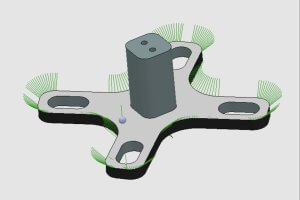
- Utilize CAM software or simulation tools to visualize and optimize toolpaths before generating G-Code.
- Consider the material properties and select appropriate cutting parameters for each operation.
- Review and refine toolpaths based on previous machining experiences and lessons learned.
- By investing time and effort into efficient toolpath planning, you can reduce machining time, improve accuracy, and optimize the overall CNC machining process.
Other Articles You Might Enjoy
- “Exploring Bead Blasting in CNC Machining”(cnc g code Eli)
Bead blasting, a popular term in the world of computer numerical control (CNC) machining, opens up new prospects for manufacturers and hobbyists alike. This article takes a closer look at…
- Understanding Bead Blasting in CNC Machining(cnc g code Jacqueline)
CNC (Computer Numerical Control) machining is a dominant method employed for multiple manufacturing systems across the globe. From healthcare to aerospace, this technology has revolutionized how we manufacture products. One…
- CNC Machining for the Renewable Energy Sector: Material Choices for Durability and Efficiency
Introduction to CNC Machining in the Renewable Energy Sector CNC (Computer Numerical Control) machining stands as a pivotal manufacturing process in the renewable energy sector, enabling the precise production of…


