Machining precision refers to the degree to which the actual geometric parameters of a machined part conform to the ideal geometric parameters (such as size, shape, and positional relationships). Improving machining precision is a crucial task in mechanical processing. This article will delve into the factors influencing machining precision and their control methods, presenting the knowledge points step-by-step to help you understand the secrets of machining precision control.
Sources of Machining Errors
Dimensional Precision, Shape Precision, and Positional Precision
Machining error refers to the deviation of the actual geometric parameters of a part from its ideal geometric parameters. To ensure machining precision, we need to evaluate the geometric parameters of machined parts from different angles. Generally, shape errors are restricted within positional tolerances, and positional errors are restricted within dimensional tolerances. When high dimensional precision is required, corresponding positional and shape precision also need to be improved.
Dimensional Precision
Dimensional precision refers to the degree to which the actual dimensions of a machined part conform to the design dimensions. For example, the closer the actual diameter and length of a shaft are to the design dimensions, the higher the dimensional precision.
Shape Precision
Shape precision refers to the degree to which the actual shape of a machined part conforms to the ideal shape. Common shape errors include roundness errors and flatness errors. For instance, a part designed to be perfectly round may have a slight elliptical shape after machining, which is a shape error.
Positional Precision
Positional precision refers to the degree to which the actual position of a machined part conforms to the design position. This includes the center distance between two holes, the perpendicularity of axes, etc. Positional errors can affect the assembly and function of parts.
Factors Affecting Machining Errors
Process System Errors
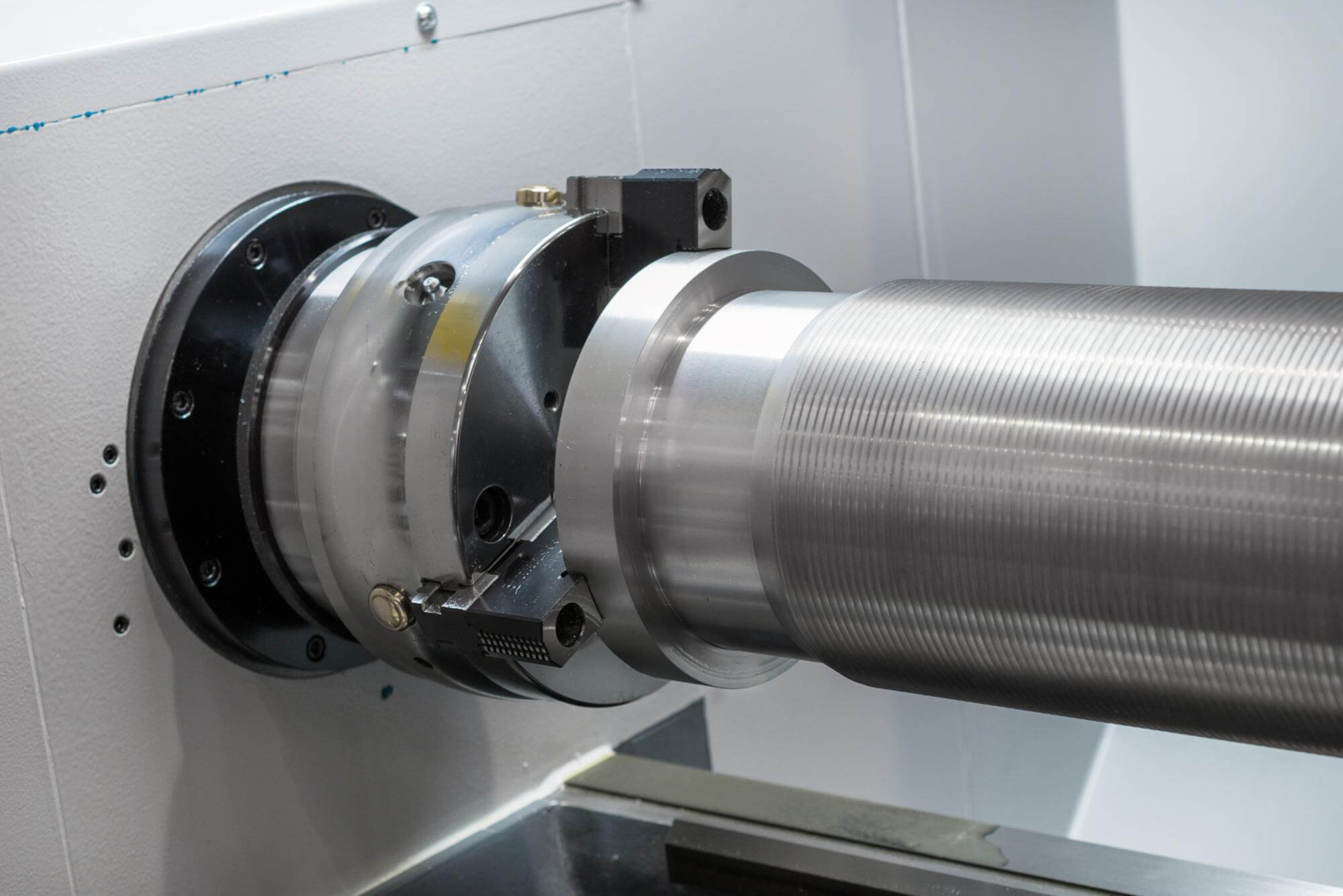
The process system refers to the complete system formed by the machine tool, cutting tool, fixture, and workpiece during machining. Various errors in the process system will reflect as machining errors. These errors can be categorized into the following types:
Geometric Errors of the Process System
Geometric errors are the manufacturing errors of the machine tool, fixtures, and cutting tools, such as the straightness error of guideways and the rotational error of the spindle. These errors directly affect the precision of machined parts.
Deformation of the Process System Due to Forces
Deformation due to forces refers to the deformation of various parts of the process system caused by external forces such as cutting forces and clamping forces during machining, which affects machining precision.
Thermal Deformation of the Process System
Thermal deformation refers to the deformation of various parts of the process system due to heat sources such as cutting heat and friction heat during machining, which affects machining precision.
Methods to Improve Machining Precision
Trial Cutting Method and Adjustment Method
Trial Cutting Method
The trial cutting method involves the worker aligning the tool for each step or before each cut, then cutting a small section and measuring its dimensions. If the dimensions are not correct, the tool position is adjusted, and another small section is cut until the required dimensions are achieved. This method has low productivity but is suitable for single-piece and small-batch production.
Adjustment Method
The adjustment method involves adjusting the relative positions and feed strokes of the machine tool, fixtures, cutting tools, and workpiece according to specified dimensions to ensure that the dimensions are automatically obtained during machining. This method does not require trial cutting, has high productivity, but lower precision, which mainly depends on the accuracy of the machine tool and fixtures and the adjustment errors.
Active Measurement Method
The active measurement method involves measuring the machining dimensions during the machining process, and stopping machining immediately when the required dimensions are reached. This method has high precision, stable quality, and high productivity, suitable for CNC machining.
Error Compensation Technology
Using Elastic Deformation to Compensate Thermal Deformation
In some high-precision machining, the elastic deformation of materials can be used to compensate for the errors caused by thermal deformation. For example, adjusting the position of the cutting tool to offset the impact of thermal deformation.
Using Geometric Errors to Compensate for Force Deformation
During machining, reasonable design of the process system structure can reduce errors caused by force deformation. For example, using high-rigidity materials and structures to increase the rigidity of the process system.
Statistical Analysis Methods
In actual production, statistical analysis methods can be used to analyze and control errors in the machining process. Through statistical analysis, the main factors affecting machining precision can be identified, and corresponding measures can be taken to control and optimize them.
Error Prevention Technology
Error prevention technology involves reducing the original errors themselves or their impact to improve machining precision. For example, reasonably adopting advanced processes and equipment, optimizing process parameters, etc.
Case Study
Below is a case study on a precision boring process, demonstrating how to analyze and control errors to improve machining precision.
Problem Description
In the precision boring process of a lathe tailstock hole, a cylindricity error (large at the head, small at the tail) appeared.
Analysis Process
- Investigation: Sampling and measurement, plotting histograms and x-R charts.
- Analysis: No abnormal fluctuations were found, but a significant constant system error existed.
- Argumentation: Checking factors such as tool thermal elongation, error replication, guide bushing runout, and boring bar bending.
- Verification: Found that the front end of the boring bar was bent by 0.1mm, causing cylindricity error.
Solutions
- Correcting Boring Bar Bending: Adjusting the position of the boring bar to reduce the error caused by bending.
- Optimizing Process Parameters: Adjusting cutting speed and feed rate to reduce the impact of tool thermal elongation.
Through the above analysis and control measures, machining precision can be effectively improved. Mastering the various factors affecting machining precision and reasonably applying error compensation and prevention technologies are crucial for improving machining quality. We hope this article provides valuable reference and help for you in controlling machining precision.
Sample Data Table
| Machining Method | Application Scope | Advantages | Disadvantages |
|---|---|---|---|
| Trial Cutting | Single-piece production | High precision, flexible | Low productivity, high worker requirements |
| Adjustment | Batch production | High productivity, easy to operate | Lower precision, dependent on equipment accuracy |
| Active Measurement | CNC machining | High precision, stable quality | High cost, complex equipment |
| Error Compensation | High-precision machining | Effective error compensation, high precision | Requires complex calculations and adjustments |
Understanding these methods and technologies can help you better control and improve machining precision, ensuring the stability and reliability of machining quality.
Other Articles You Might Enjoy
- Elevating Precision Standards through Chamfer in CNC Machining
1. Introduction: The Pursuit of Unparalleled Precision In the realm of CNC machining, precision is paramount. This section introduces the article by exploring the significance of precision in manufacturing and…
- Aerospace Machining: Definition, Materials & Precision Machining Process
Aerospace machining is a crucial aspect of the aerospace industry, with the global market for aerospace machining services expected to surpass $8 billion by 2026. In fact, aerospace manufacturing is…
- Precision Prowess: Unveiling the Advantages of China CNC Machining
1. Introduction: The Role of Precision in Manufacturing Excellence In this introductory section, we delve into the critical role that precision plays in manufacturing and set the stage for an…
- Revolutionizing CNC Machining for Complex Aerospace Assemblies
Introduction to CNC Machining in Aerospace Assemblies Computer Numerical Control (CNC) machining represents a significant technological development playing a notable role in the creation of complex aerospace assemblies. CNC machining…
- The Role of Prototype Machining in Accelerating Product Development
Introduction: The Importance and Definition of Prototype Machining Prototype machining is a critical element advancing product development. It involves the technique of manufacturing an early model or sample, known as…
- Maximizing Precision in CNC Machining: Techniques and Tips
Importance of Precision in CNC Machining Precision is an fundamental component in the field of Computer Numerical Control (CNC) machining. It entails producing parts that are not only accurate but…


