
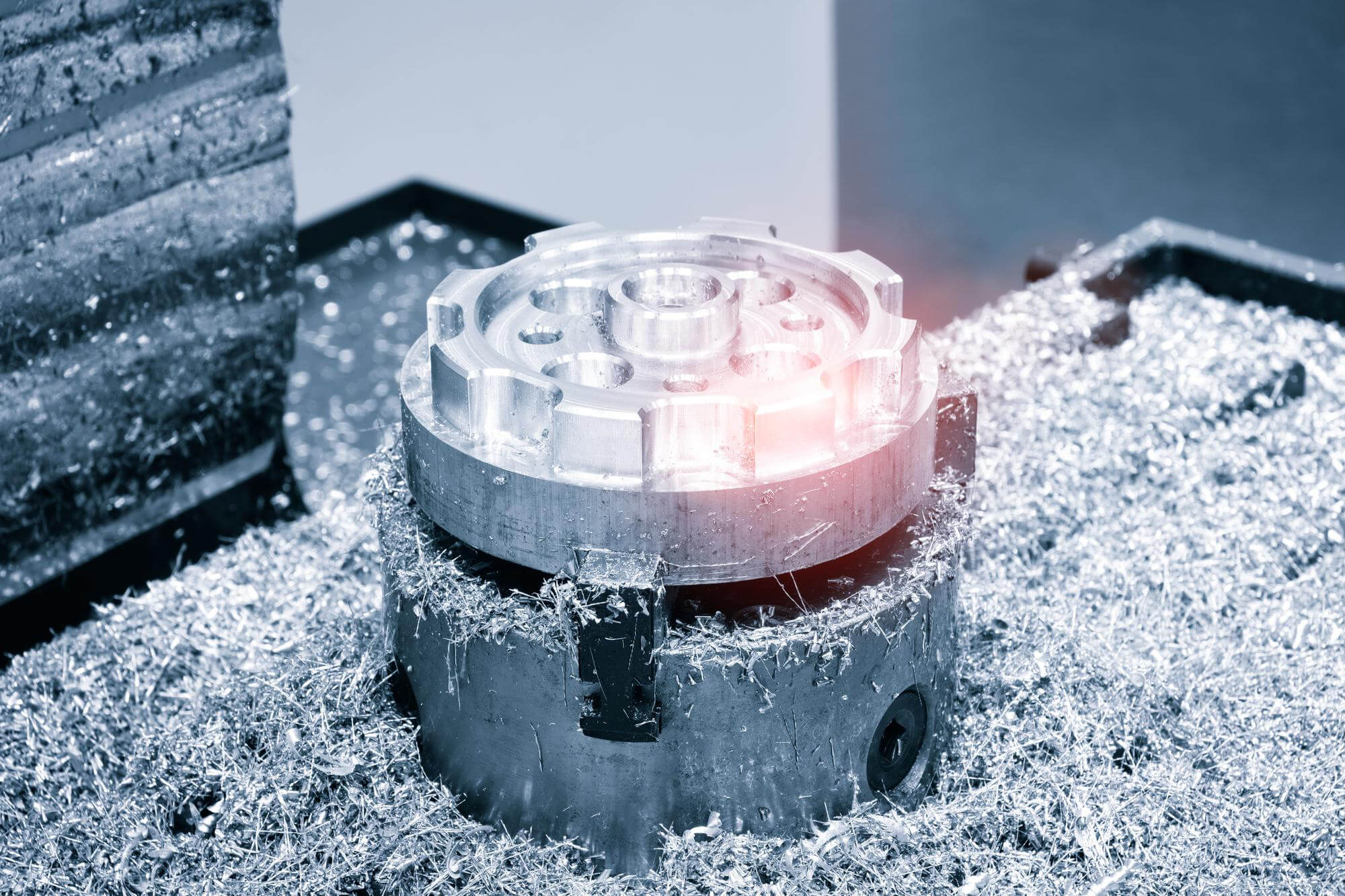
Milling, especially flat milling, is an essential process in CNC machining. To achieve the best results, several factors need to be considered, including tool selection, cutting angles, and programming techniques. This guide delves into these aspects, offering practical insights and tips for optimizing your CNC machining process.
Cutting Considerations
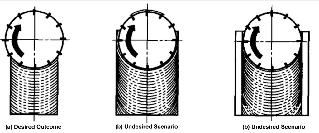
When planning flat milling, it’s crucial to understand how the tool will perform under different conditions. For example, unless the tool is specially designed with the correct insert geometry, shape, and grade, it’s best to avoid milling workpieces with a width equal to or slightly larger than the tool diameter. Full-width milling can quickly wear out the insert cutting edges and cause chips to stick to the insert, affecting the surface quality of the workpiece and potentially leading to premature insert failure and increased processing costs. Figure 1 illustrates the correct and incorrect relationships between tool diameter and workpiece width in flat milling.
Figure 1:
Tool Diameter and Workpiece Width Relationship
- Desired Outcome: Proper tool diameter to workpiece width ratio
- Undesired Outcome: Full-width milling causing rapid tool wear
This relationship is crucial irrespective of the tool’s actual entry into the material. In CNC programming for flat milling, the most important consideration is the cutter entry angle.
Entry Angle
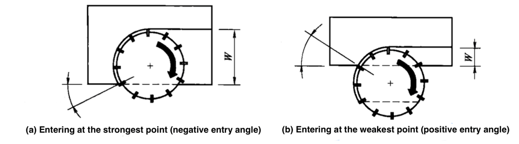
The entry angle of a flat milling cutter is determined by the position of the tool’s centerline relative to the workpiece edge. Avoid aligning the tool centerline with the workpiece centerline, as this neutral position can cause vibration and poor machining quality. Instead, offset the tool to avoid direct alignment, ensuring better stability and cutting performance. Figure 2 shows two types of entry angles and their effects.
Entry Angle Types
- Negative Entry Angle: Preferred as the strongest point of the insert bears the cutting force, extending tool life.
- Positive Entry Angle: Not recommended as the weakest point of the insert bears the force, leading to potential tool damage.
Figure 2:
Milling Modes
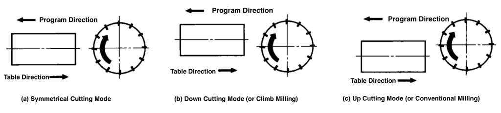
In CNC milling, the direction of the cutting movement relative to the workpiece is vital. There are three traditional milling modes:
- Symmetrical Milling Mode: The tool moves along the centerline of the slot or surface.
- Conventional Milling Mode (Up Milling): The tool moves on one side of the centerline.
- Climb Milling Mode (Down Milling): The tool moves on the other side of the centerline.
Climb milling is often the best choice for most flat milling operations. Figure 34 illustrates these milling modes.
Figure 3:
Insert Quantity
Flat milling cutters usually have multiple inserts, known as multi-tooth cutters. Traditional fly cutters, with only one cutting insert, are not common in CNC. The relationship between the number of inserts and the effective diameter of the tool is referred to as tool density. Based on tool density, flat milling cutters can be categorized as:
- Low Density: Inserts spaced far apart
- Medium Density: Average spacing between inserts
- High Density: Inserts spaced close together
Choosing the right density ensures sufficient clearance for chip removal, preventing tool clogging. At any time, at least one insert should be in contact with the material to avoid tool or machine damage due to sudden cutting interruptions.
Programming Tips
While flat milling is a straightforward operation, understanding some basic principles can enhance programming. Consider the tool path from start to finish:
- Move the tool to the required depth outside the workpiece.
- Change tool direction outside the workpiece for better surface quality.
- Ensure the tool midpoint remains within the workpiece area for optimal cutting conditions.
- Select a tool diameter typically 1.5 times the cutting width.
For example, in single-pass flat milling using a 5x3x1 steel plate, the final thickness should be 0.800 inches, as shown in Figure 28-6. The critical decisions include choosing the tool diameter and determining the start and end points. A 5.0-inch diameter milling cutter is suitable for a 3-inch wide workpiece, considering an overlap on both sides. The start point could be X7.75 Y1.0, and the end point could be X-2.75 Y1.0, as illustrated in Figure 28-7.
Single Pass Flat Milling Program Example
O2801
N1 G20
N2 G17 G40 G80
N3 G90 G54 G00 X7.75 Y1.0 S344 M03
N4 G43 Z1.0 H01
N5 G01 Z0 F50.0 M08
N6 X-2.75 F21.0
N7 G00 Z1.0 M09
N8 G28 X-2.75 Y1.0 Z1.0
N9 M30
Multiple Pass Flat Milling
In multiple pass flat milling, the same rules apply. If the tool diameter is too small to remove all material in one pass, multiple passes at the same depth are required. The most common methods are unidirectional multiple pass cutting and bidirectional multiple pass cutting (zigzag cutting).
- Unidirectional Multiple Pass Cutting: The tool starts at the same position on one axis and moves to different positions on another axis.
- Bidirectional Multiple Pass Cutting: Also known as zigzag cutting, this method is more efficient as it alternates climb and conventional milling.
Figures 28-8 and 28-9 illustrate these methods.
Example of Multiple Pass Flat Milling Program
O2802
N1 G20
N2 G17 G40 G80
N3 G90 G54 G00 X0.75 Y-2.75 S344 M03
N4 G43 Z1.0 H01
N5 G01 Z0 F50.0 M08
N6 Y8.75 F21.0
N7 G00 X12.25
N8 G01 Y-2.75
N9 G00 X4.0
N10 G01 Y8.75
N11 G00 X8.9
N12 G01 Y-2.75
N13 G00 Z1.0 M09
N14 G28 X8.75 Y-2.75 Z1.0
N15 M30
Optimizing Milling Processes
For enhanced efficiency, consider using a single mode (preferably climb milling) and perform circular or spiral movements along the XY axes. This method ensures consistent cutting width and optimal conditions.
Data Table: Tool Diameter vs. Cutting Width
| Tool Diameter (inches) | Cutting Width (inches) | Mode | Insert Density |
|---|---|---|---|
| 3.0 | 2.0 | Climb | Medium |
| 4.0 | 2.5 | Climb/Up | High |
| 5.0 | 3.25 | Climb | Medium |
Conclusion
By understanding and applying these concepts in flat milling, you can significantly improve the performance and longevity of your CNC tools. Always consider the specific requirements of your material and task to determine the best approach.


 Afrikaans
 Albanian
 Amharic
 Arabic
 Armenian
 Azerbaijani
 Basque
 Belarusian
 Bengali
 Bosnian
 Bulgarian
 Catalan
 Cebuano
 Chichewa
 Chinese (Simplified)
 Chinese (Traditional)
 Corsican
 Croatian
 Czech
Czech Danish
 Dutch
Dutch English
 Esperanto
 Estonian
 Filipino
 Finnish
 French
 Frisian
 Galician
 Georgian
 German
 Greek
Greek Gujarati
 Haitian Creole
 Hausa
Hausa Hawaiian
 Hebrew
 Hindi
Hindi Hmong
Hmong Hungarian
 Icelandic
 Igbo
Igbo Indonesian
 Irish
Irish Italian
 Japanese
 Javanese
 Kannada
 Kazakh
 Khmer
Khmer Korean
 Kurdish (Kurmanji)
 Kyrgyz
 Lao
Lao Latin
Latin Latvian
 Lithuanian
 Luxembourgish
 Macedonian
 Malagasy
 Malay
Malay Malayalam
 Maltese
 Maori
Maori Marathi
 Mongolian
 Myanmar (Burmese)
 Nepali
 Norwegian
 Pashto
 Persian
 Polish
 Portuguese
 Punjabi
 Romanian
 Russian
 Samoan
 Scottish Gaelic
 Serbian
 Sesotho
 Shona
Shona Sindhi
 Sinhala
 Slovak
 Slovenian
 Somali
 Spanish
 Sundanese
 Swahili
 Swedish
 Tajik
Tajik Tamil
Tamil Telugu
 Thai
Thai Turkish
 Ukrainian
 Urdu
Urdu Uzbek
Uzbek Vietnamese
 Welsh
Welsh Xhosa
Xhosa Yiddish
 Yoruba
 Zulu
Zulu