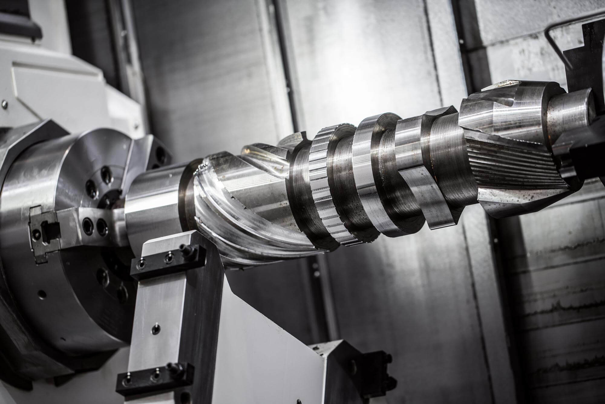
Face milling is an essential operation in CNC machining, aimed at controlling the height of the workpiece and ensuring a smooth surface finish. This process often uses multi-tooth cutters, known as face mills. While face milling might seem straightforward, it involves several crucial considerations to ensure optimal performance and desired outcomes. This guide will delve into the essential aspects of face milling, covering cutter selection, initial positioning, and important technical considerations.
Choosing the Right Face Mill
Selecting the appropriate face mill is paramount for effective CNC machining. The typical face mill used in CNC operations is a multi-tooth tool with replaceable carbide inserts. High-speed steel (HSS) face mills are less common in CNC work due to their lower efficiency compared to carbide inserts.
Key Factors in Face Mill Selection:
- CNC Machine Specifications: The machine’s power and condition play a significant role in determining the suitable face mill.
- Workpiece Material: Different materials require different types of face mills.
- Preparation and Support: Ensuring the workpiece is well-prepared and securely supported is crucial for precise milling.
- Mounting Method: Proper mounting of the tool ensures stability and accuracy during the milling process.
- Cutter Structure: The design of the cutter affects the milling operation and its efficiency.
- Diameter of Face Mill: The cutter’s diameter should be appropriate for the width of the material being milled.
- Number and Geometry of Inserts: The inserts’ design and arrangement significantly influence the milling process.
Selecting the Cutter Diameter
The diameter of the face mill is a critical factor. Ideally, for single-pass face milling, the cutter should be 1.3 to 1.6 times the width of the material. For example, for a 2.5-inch wide material, a 4.0-inch face mill is optimal. This ratio ensures effective chip formation and removal.
When multiple passes are necessary, selecting the largest possible cutter diameter is beneficial, considering the machine’s power, the cutter and insert geometry, and the depth and width of each pass.
Geometry of Inserts
Understanding the geometry of inserts is essential for selecting the right tool. The inserts’ geometry and their mounting determine their position in the material, affecting the cutting quality. Inserts can be categorized based on the rake angle of the cutter:
- Positive Rake: Requires less power, suitable for machines with lower power, and works well with steel materials.
- Negative Rake: Stronger cutting edges, requires more power, ideal for cast iron and harder materials, but may produce poor chip formation with steel.
- Double Negative Rake: Suitable for high-power machines and robust setups, useful for machining hard materials.
- Combination Rake: Offers the benefits of both positive and negative rake angles, ideal for creating spiral chips and improving chip evacuation.
Starting Position and Milling Technique
The initial position of the face mill relative to the workpiece is crucial. Correct positioning ensures effective material removal and a smooth finish. Typically, the face mill should start slightly off the workpiece to allow gradual engagement with the material.
Practical Tips for Face Milling
- Cutter Speed and Feed Rate: Adjusting the speed and feed rate based on the material and cutter type is essential for optimal performance.
- Depth of Cut: Determining the appropriate depth of cut for each pass ensures efficient material removal without overloading the cutter or the machine.
- Coolant Usage: Proper use of coolant helps in chip evacuation and maintains the cutter’s temperature, prolonging its life.
- Insert Maintenance: Regularly inspecting and replacing worn inserts ensures consistent milling quality and prevents damage to the cutter and the workpiece.
Table of Common Face Mill Diameters and Insert Types
| Material Width (in) | Recommended Face Mill Diameter (in) | Insert Type |
|---|---|---|
| 1.0 – 2.0 | 1.3 – 3.2 | Positive Rake, Single-Sided |
| 2.1 – 3.0 | 2.7 – 4.8 | Negative Rake, Double-Sided |
| 3.1 – 4.0 | 4.0 – 6.4 | Combination Rake, Spiral |
| 4.1 – 5.0 | 5.3 – 8.0 | Positive Rake, Single-Sided |
| 5.1 – 6.0 | 6.7 – 9.6 | Negative Rake, Double-Sided |
By following these guidelines and understanding the key elements of face milling, you can achieve superior surface finishes and precise height control in your CNC machined parts.
Other Articles You Might Enjoy
- Understanding Bead Blasting in CNC Machining(face milling Rex)
Bead blasting, an abrasive process used within various manufacturing industries, plays a critical role particularly with Computer Numerical Control (CNC) machining to create precise, smooth finished components. Whether it’s for…
- Rapid Prototyping with CNC Machining: High-Quality Stainless Steel Parts
Rapid Prototyping and CNC Machining: A Brief Overview Both Rapid Prototyping and Computer Numerically Controlled (CNC) Machining represent transformative technologies within the realm of manufacturing. Rapid Prototyping refers to techniques…
- Exploring the Limits of CNC Machining with Exotic Metal Alloys
Introduction: CNC Machining and Exotic Metal Alloys CNC machining involves the use of computers to control machine tools, enabling precision manufacturing. A critical aspect of this technology lies in material…
- Prototype CNC Machining Services: Custom Aluminum Solutions
Introduction to Prototype CNC Machining and Custom Aluminum Solutions Prototype CNC (Computer Numerical Control) machining is a manufacturing technique that entails the use of pre-programmed computer software to dictate the…
- Revolutionizing Renewable Energy with CNC Machined Components
Introduction: Renewable Energy and CNC Machined Components Renewable energy harnesses power from natural sources such as the sun, wind, and water, making it a sustainable and eco-friendly alternative to traditional…
- New Trends in China CNC Machining: Combining Bead Blasting with Face Milling
Opening: Exploring the Innovative Trends in China CNC Machining The landscape of China's manufacturing industry has been profoundly transformed by advancements in CNC (Computer Numerical Control) machining. As the backbone…


