CNC machining is a subtractive manufacturing process that utilizes programmed codes to control the movement of the tool axis. These codes encompass cutting parameters such as tool movement, spindle speeds, feeds, RPMs, and more.
Proper consideration of these parameters is crucial when designing products for CNC machining operations. They play a pivotal role in optimizing various aspects of the machining process, including tool life, power consumption, machining time, and surface roughness of the finished products.
Engineers and machinists must have a comprehensive understanding of cutting speed and feed rate, along with the differences between them, to derive optimal values. Let’s explore these concepts in more detail.
What Is Feed Rate?
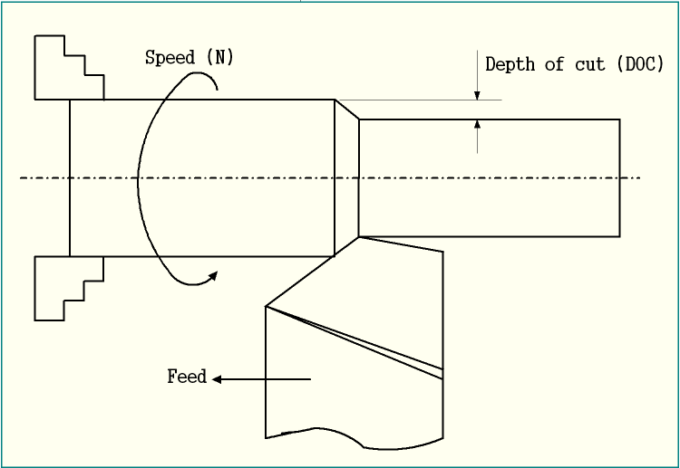
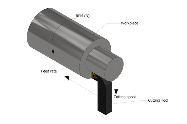
Feed rate refers to the distance traveled by the cutting tool during one revolution of the spindle. It is also known as the cutting tool engagement speed. In CNC milling operations, feed rate is typically measured in inches per minute (IPM) or millimeters per minute (mm/min). For boring and turning operations, it can be measured in inches per revolution (IPR) or millimeters per revolution (mm/rev).

The variation in feed rates depends on factors such as the type of blank material (e.g., steel, wood, aluminum, stainless steel), the tool material (e.g., HSS cutting tool, ceramic, cermet), surface finish requirements, and the characteristics of the CNC machine.
The feed rate significantly influences the aesthetics of machined products, making the optimization of this parameter crucial in CNC machining processes.
Selection of Optimum Feed Rate
The feed rate directly impacts safety, productivity, tool life, and product quality in CNC machining. Consider the following factors when selecting the feed rate:
1. Productivity: Higher feed rates can enhance productivity but may result in a loss of surface quality. Alternatively, maintaining a stable feed rate allows for increased cutting speeds.
2. Surface Finish: Lower feed rates generally yield better surface finish. Coarser feed rates are suitable for rough cuts. For example, a feed rate of 0.01-0.05mm/rev is commonly used for finishing operations, while 0.1-0.3mm/rev may be suitable for rough CNC turning operations.
3. Feed Rate Limit: Machine tools have specific feed rate limits, indicated by the minimum and maximum range. It is important to operate within these limits. Conventional lathe machine tools offer only a few feed rate options within the given range.
4. Cutting Tool Geometry: Besides the feed rate, the tool geometry also affects surface finish. Higher values for tool geometry are preferred if the specific geometry permits.
5. Machine Tool Capability: Higher feed rates can generate increased cutting forces and vibrations. The feed rate must be chosen considering the machine tool’s ability to absorb and transmit these forces and vibrations.
What Is Cutting Speed?
Cutting speed refers to the relative velocity between the cutting tool and the workpiece surface. It is also known as surface speed. This value represents the linear distance, measured in meters per minute (m/min) or feet per minute (ft/min), that the cutting tool material moves over the workpiece surface during the cutting process.

Cutting speed plays a significant role in determining important parameters in CNC machining, including power consumption, cutting temperature, and tool life. Different materials, such as high carbon steel, low carbon steel, aluminum, and plastics, have varying cutting speed values. Certain tools or processes, such as threading tools and knurling tools, may operate at lower cutting speeds.
Selection of Optimum Cutting Speed
To achieve the best results in CNC machining, determining the optimum cutting speed is crucial. Consider the following factors when selecting the cutting speed:
1. Workpiece Hardness: Harder materials require slower cutting speeds to prevent rapid tool wear. For example, machining titanium requires a lower cutting speed compared to machining steel.
| Material | Turning | Drilling | Reaming | End Milling | |
| Aluminum | 400-1000 | 250-600 | 100-300 | 600 | |
| Brass | 225-300 | 150-300 | 130-200 | / | |
| Bronze | 150-225 | 100-250 | 75-180 | 125-250 | |
| Cast Iron | Soft | 100-150 | 75-150 | 60-100 | 60 |
| Medium | 75-120 | 70-110 | 35-65 | / | |
| Hard | 50-90 | 60-100 | 20-55 | 50 | |
| Copper | 100-120 | 60-100 | 40-60 | / | |
| Magnesium | 600-1200 | 300-650 | 150-350 | / | |
| Stainless Steel | Free Machining | 100-150 | 65-100 | 35-85 | 35-55 |
| Other Grades | 40-85 | 15-50 | 15-30 | 35-55 | |
| Carbon & Alloy | Free Machining | 125-200 | 100-145 | 60-100 | 50-75 |
| Less than 0.3% C | 75-175 | 70-120 | 50-90 | 50-75 | |
| 0.4 – 0.6% C | 65-120 | 55-90 | 45-70 | 50-75 | |
| More than 0.6% C | 60-80 | 40-60 | 40-50 | 50-75 | |
| Titanium | 25-55 | 30-60 | 10-20 | 25 | |
2. Cutting Tool Strength: The cutting edge tool strength is a key factor in determining permissible cutting speeds. Cutting tools made of high-strength materials like diamond and carbon boron nitride can withstand higher cutting speeds, while high-speed steel tools are suitable for lower cutting speeds.
3. Tool Life: Higher cutting speeds accelerate the wear of softer cutting tool materials, resulting in shorter tool life. The desired tool life should be considered alongside parameters such as tool cost and the quantity of parts produced. If these parameters fall within acceptable limits, higher cutting speeds can be utilized.
The Importance of Speeds and Feeds in Machining
Speeds and feeds play a crucial role in machining as they determine the rate and amount of material removal. They significantly impact tool life, surface finish, and overall machining efficiency.
One crucial factor influenced by speeds and feeds is cutting temperature, as higher temperatures can adversely affect tool life and surface roughness. Additionally, the effects of incorrect speeds and feeds are more noticeable when working with harder materials that have narrower error margins, such as titanium or Inconel.
Maintaining the appropriate balance between cutting speed and feed rate is essential to avoid tool breakage and achieve optimal results. Inadequate speeds and feeds can result in improper material cutting, burrs, or other surface imperfections.
Differentiating Feed Rate and Cutting Speed
While both feed rate and cutting speed impact machine performance, they represent distinct aspects of the machining process. Understanding their differences is crucial for maximizing the capabilities of CNC machines. Here are the key distinctions:
- The main difference between feed rate and cutting speed is that feed rate represents the speed at which the tool moves through the workpiece, while cutting speed represents the speed at which the cutting edge of the tool moves.
- Cutting speed provides a generatrix and is typically measured in m/min or ft/min (denoted as Vc), while feed rate provides a directrix and is generally measured in mm/rev or mm/min (denoted as s or f).
- Cutting speed influences cutting force and power consumption during machining, whereas the feed rate does not have a direct influence on these factors.
- Cutting speed does not have a significant role in deviating the chip direction from orthogonal. However, in almost every case, the feed rate influences the flow of the actual chip direction.
- The feed rate has a minimal impact on cutting temperature, tool wear, and tool life, while cutting speed has a more substantial impact on these factors.
- The generation of scallop or feed marks on the machined surface does not have a direct involvement of cutting speed. However, the surface roughness represented by scallop marks on the finished product surface directly relates to the feed rate.
Refer to the chart below for a visual representation of the differences between cutting speed and feed rate:
| Parameter | Cutting Speed | Feed Rate |
|---|---|---|
| Measurement | m/min or ft/min | mm/rev or mm/min |
| Cutting Force | Influences | Does not influence |
| Chip Direction | Not involved | Influences |
| Cutting Temperature | Significantly | Less impacted |
| Tool Wear | Significantly | Less impacted |
| Scallop/Feed Marks | Not involved | Direct involvement |
How to Determine Feed Rate and Cutting Speed
The provided chart encompasses all the necessary parameters to determine cutting speed and feed rate. To calculate these values, the spindle speed is a fundamental requirement. Two methods can be employed to determine the final feed rate: by determining the feed per tooth and subsequently using this value to calculate the overall feed rate.
Additional Considerations
- Spindle Speed Limit: Defining the cutter speed in RPM requires knowledge of the surface feet per minute (SFM) based on the material and cutter diameter. In certain cases, the calculated speed may yield unfeasible results. In such instances, machinists should operate the tool at the machine’s maximum speed while maintaining the required chip load for the given diameter to achieve optimal parameters.
- Non-Linear Path: Feed rates are generally assumed to involve linear motion, but there are cases where feed rates need to be considered in arc or circular interpolation paths, such as outer diameter or inner diameter machining. As the depth of cut increases, the angle of engagement on the tool increases, leading to a non-linear path. The tool’s engagement is higher for internal corners compared to external corners.
- Interaction of Cutting Velocity and Feed Rate: During machining, the cutting tool compresses the workpiece surface and removes a thin layer of material in the form of a chip. The required compressive force is transmitted by the primary relative velocity, which is generated by the cutting velocity. Another synchronous motion, known as the feed motion, must be provided to the cutter or workpiece (varies depending on milling operations) along the intended direction to remove material from the total workpiece surface. The coordinated actions of feed rate, cutting velocity, and feed motion satisfy the basic requirements of machining.
Conclusion
Speeds and feeds play a crucial role in optimizing various parameters in CNC machining, including tool life, power consumption, machining time, and surface roughness. Understanding the interplay between cutting speed and feed rate is of great benefit in the production of CNC machined parts. Therefore, engineers and machinists must have a comprehensive understanding of these concepts.
At Want.Net, our experienced engineers and machinists are dedicated to meeting diverse machining needs and delivering the desired parts and products. If you have any concerns regarding cutting speeds and feed rates in your CNC machined parts, feel free to contact us today. We are committed to ensuring that you always receive the best-machined parts you expect.
Frequently Asked Questions
Q: Is cutting speed the same as feed rate? A: No, cutting speed and feed rate are different. Cutting speed refers to the speed at which the cutting tool moves through the material, while feed rate represents the speed at which the material moves past the cutting tool.
Q: What does SFM mean in machining? A: SFM stands for Surface Feet per Minute, which is a common measurement of cutting speed in machining. SFM represents the number of feet a tool can travel across a workpiece in one minute. Higher SFM values indicate faster cutting speeds.
Q: Why do engineers and machinists need to consider cutting speeds and feed rates during CNC machining? A: Engineers and machinists must consider cutting speeds and feed rates during CNC machining because these parameters directly impact the quality of the finished product. Insufficient cutting speed can result in improper material cutting and the presence of burrs or surface imperfections.
Recommended Reads:
- What is High-Speed Machining?
- CNC Cutting vs. Laser Cutting: Which Manufacturing Process is Right for You?
- Electrical Discharge Machining: Exploring Construction, Applications, Pros, and Cons
- Bringing Your Design to Life: Prototyping Mechanical Watch Parts
Other Articles You Might Enjoy
- Beyond Cutting: Exploring the Multifaceted CNC Machining Process
1. Introduction: Unveiling the Layers of CNC Machining In this introductory section, we peel back the layers of the CNC machining process, going beyond the traditional understanding of cutting. It…
- Exploring Bead Blasting In CNC Machining(cnc cutting tools Hale)
Bead blasting is a crucial technique applied extensively in the realm of Computer Numerical Control (CNC) machining. This process transforms the exterior aesthetics and surface quality of machined parts, augmenting…
- Comparing Machinability of Various Tool Steels: What's the Best Choice?
Understanding Tool Steels and their Machinability Tool steels are referred to as an extensive variety of carbon and alloy steels known for their distinctive hardness, abrasion resistance, and ability to…


