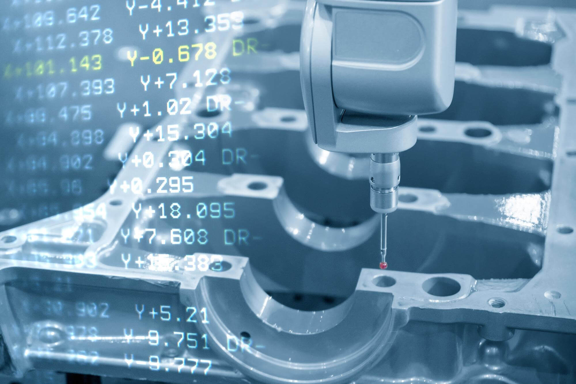
CNC programming is an essential skill in modern manufacturing, allowing precise control over machining processes. One of the core elements of CNC programming is the word address format and the structure of program blocks. Understanding these concepts is crucial for creating efficient and error-free CNC programs.
Word Address Format in CNC Programming
The word address format is the standard method for encoding instructions in CNC programs. It consists of a letter followed by one or more numbers, sometimes including symbols like negative signs or decimal points. Each combination represents a specific command or data point used by the CNC controller to execute precise machining operations.
Common Word Addresses:
- G codes: Preparatory functions (e.g., G01 for linear interpolation)
- M codes: Miscellaneous functions (e.g., M30 for program end)
- X, Y, Z: Coordinate axes
- F: Feed rate
- S: Spindle speed
- T: Tool selection
- N: Sequence number
Example of word addresses:
- G01 X15.75 Y30.0 Z-5.14 F120.0 S2500 T01
Structure of Program Blocks
A CNC program is composed of multiple program blocks, each containing a set of word addresses that define specific machining actions. These blocks are executed sequentially to carry out complex machining tasks.
Components of a Program Block:
- Sequence Number (N): An optional identifier that helps organize and reference specific blocks.
- G Codes: Instructions for motion and path control.
- Coordinate Words (X, Y, Z): Define the target positions for the tool.
- Feed Rate (F): Specifies the speed at which the tool moves through the material.
- Spindle Speed (S): Controls the rotation speed of the cutting tool.
- Tool Selection (T): Chooses the appropriate tool for the operation.
- Miscellaneous Codes (M): Perform auxiliary functions like starting the spindle or turning on coolant.
Example of a program block:
- N10 G01 X50.0 Y25.0 Z-10.0 F150.0 S2000 M08
Practical Example: Machining a Simple Part
Let’s walk through the creation of a CNC program for machining a simple rectangular part with a hole.
- Initial Setup:
- Material: Aluminum
- Tool: 10mm end mill
2.Program:
   N10 G90 G21 (Absolute positioning, metric units)
   N20 T01 M06 (Select tool 1 and change tool)
   N30 S1500 M03 (Set spindle speed and start spindle)
   N40 G00 X0 Y0 Z5 (Move to starting position above the part)
   N50 G01 Z-5 F100 (Feed to cutting depth)
   N60 G01 X50 (Cut along X-axis)
   N70 G01 Y25 (Cut along Y-axis)
   N80 G01 X0 (Return along X-axis)
   N90 G01 Y0 (Return along Y-axis)
   N100 G00 Z5 (Retract tool)
   N110 G00 X25 Y12.5 (Move to hole position)
   N120 G01 Z-5 (Feed to cutting depth)
   N130 G02 I0 J12.5 (Circular interpolation to create hole)
   N140 G00 Z5 (Retract tool)
   N150 M30 (End of program)
This simple example demonstrates how to organize a CNC program using word address format and program blocks to achieve precise machining.
Best Practices for CNC Programming
- Consistent Formatting: Keep a consistent format for easier reading and troubleshooting.
- Commenting: Use comments to explain complex sections of the code (e.g.,
(Cut along X-axis)). - Sequence Numbers: Use sequence numbers for easier reference and editing.
- Verification: Always simulate the program in a virtual environment to catch errors before actual machining.
Other Articles You Might Enjoy
- Diving into Vertical CNC Machining Centers: From Programming to Specifications
When you step into a machine shop, the hum of CNC machines is a familiar sound. Among these, the vertical CNC machining center is a workhorse, particularly when it comes…
- Mechanical Dance: The Journey of CNC Machining Parts Program Design
The world of CNC machining is a fascinating blend of precision, technology, and artistry. At the heart of this intricate dance lies the journey of program design, a crucial process…
- The Role of Precision in CNC Machining: How Tight Tolerances Impact Cost and Quality?
Introduction: Understanding Precision in CNC Machining In manufacturing contexts, precision is epitomized by Computer Numerical Control (CNC) machining. In essence, CNC machining is a process utilized widely within the manufacturing…
- The Evolution of CNC Programming: Past, Present, and Future
The Evolution of CNC Programming: Past, Present, and Future Computer Numerical Control (CNC) is a high-tech innovation that uses programming to automate machine tools. It all began in the 1950s…
- Program Data Multipliers in CNC Machining Parts: Optimizing Speed and Feed Rates
In the realm of CNC machining, fine-tuning the machine's performance can lead to significant improvements in both efficiency and quality. One crucial aspect of this tuning process involves the use…
- Precision from Blueprints to Finished Parts: The CNC Machining Program Design Unveiled
When it comes to CNC machining, designing a perfect program is like choreographing a dance. It starts with detailed planning, and each step must be carefully considered. The goal is…


