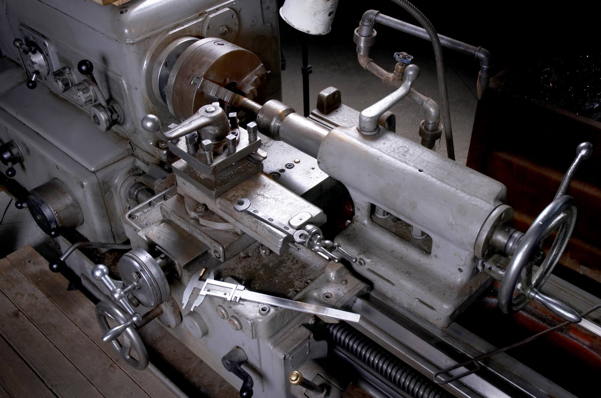
In the world of mold and aerospace machining, two-dimensional cavity machining stands out as one of the most material-intensive and time-consuming processes. For example, the machining of integral wall panels in aerospace involves removing up to 90% of the material. These panels often have numerous triangular and rectangular cavities, making the task even more demanding. Achieving high precision, efficiency, and reliability in machining such large-volume, high-material-removal components is a critical goal in aerospace manufacturing. High-speed cutting is key to solving these challenges, and spiral milling offers an effective method for improving efficiency and precision in these operations.
Algorithm Introduction
The process of planning a planar spiral toolpath involves several steps. Initially, a two-dimensional steady-state temperature field is introduced into the cavity machining area. By applying the two-dimensional steady-state conditions and using the finite element method to solve the temperature distribution, a temperature field within the cavity can be obtained. This temperature field yields a series of closed annular isothermal lines. Interpolating these isothermal lines results in the desired spiral toolpath. Since the isothermal lines derived from the two-dimensional steady-state temperature field exhibit second-order continuity, they are ideal for high-speed feed toolpath planning.
Steps for Planning Spiral Toolpaths:
- Determine Machining Area: Based on the tool radius and machining allowance, the target area for machining is defined. Within this area, two-dimensional steady-state conditions are applied.
- Discretize the Machining Area: Using the Delaunay algorithm, the area is divided into triangular meshes for finite element analysis.
- Solve Temperature Field: Apply the finite element method to solve the two-dimensional steady-state temperature field, resulting in a temperature map of the machining area.
- Extract Isothermal Lines: Based on the temperature distribution and the desired cut width, extract a series of isothermal lines.
- Generate Spiral Toolpath: Interpolate these isothermal lines to create a smooth, continuous spiral toolpath.
Solving the Heat Conduction Partial Differential Equation
In a two-dimensional Cartesian coordinate system, heat conduction follows Fourier’s law. Under steady-state conditions, the energy conservation law can be applied to derive the heat diffusion equation:
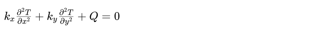
Where:
- ( T ) is the temperature,
- ( Kx ) and ( Ky ) are the thermal conductivities in the ( x ) and ( y ) directions, respectively,
- ( Q ) is the heat generated per unit area.
To simplify, we assume equal thermal conductivities in both directions and normalize the boundary temperature to zero, reducing the equation to:
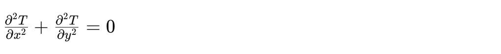
Solving this equation provides a temperature distribution ( T(x, y) ) over the machining area. By extracting the isothermal lines from this distribution and projecting them onto the machining plane, we obtain the continuous, smooth curves necessary for high-speed spiral milling.
Discretizing the Machining Area
To apply the finite element method, the machining area must first be discretized. This involves treating the surface as a polygon in the ( xy )-plane. Points are sampled in increments along the axes, creating a set of points representing the polygon’s surface. Points outside the polygon are discarded, while those close to the boundary are refined for better mesh quality. The result is a set of points ready for Delaunay triangulation.
Delaunay Triangulation Algorithm:
- Initialize with a large outer triangle: Ensures all points lie within this initial boundary.
- Insert points sequentially: Maintain and update the Delaunay triangulation for each point insertion.
- Flip edges as needed: Ensure all edges conform to the Delaunay condition, maximizing the minimum angles of triangles.
This process results in a high-quality triangular mesh suitable for finite element analysis.
Finite Element Method (FEM) Solution
With the Delaunay triangulation completed, the finite element method is used to solve the heat conduction equation over the mesh. Each triangular element contributes to the overall temperature distribution, and the solution yields a temperature field across the entire machining area.
Finite Element Analysis Steps:
- Construct basis functions: Define linear basis functions for each triangular element.
- Assemble the global stiffness matrix: Combine contributions from all elements.
- Solve the linear system: Use boundary conditions to solve for temperature values at each mesh node.
- Normalize and interpolate: Normalize the temperature values and interpolate to extract isothermal lines.
Spiral Toolpath Planning
Using the temperature field, the spiral toolpath is generated by tracing the isothermal lines. Starting from the center, where the temperature is highest, the toolpath spirals outward, maintaining a constant cut width. This approach ensures smooth transitions and continuous tool motion, reducing machine vibration and improving precision.
Steps for Toolpath Generation:
- Identify starting point: The center of the spiral corresponds to the highest temperature point.
- Trace isothermal lines: Extract points along the isothermal lines at regular intervals corresponding to the desired cut width.
- Create toolpath segments: Connect these points to form the continuous spiral path.
- Smooth transitions: Ensure smooth transitions between segments to maintain high-speed feed rates.
This method offers several advantages, including reduced machining time, improved surface finish, and enhanced tool life. By minimizing rapid accelerations and decelerations, the spiral toolpath maintains consistent cutting conditions, leading to better overall machining performance.
Data Table for Reference
Here is a table summarizing the key parameters and their effects on the spiral milling process:
| Parameter | Description | Effect on Process |
|---|---|---|
| Tool Radius | Radius of the milling tool | Determines the size of the cutting area |
| Machining Allowance | Material to be removed | Affects the depth and width of each cut |
| Cut Width | Width of each cut pass | Influences the smoothness of the toolpath |
| Temperature Field | Distribution of temperatures in the machining area | Used to derive isothermal lines for toolpath |
| Delaunay Triangulation | Method for mesh generation | Ensures high-quality mesh for FEM analysis |
| Finite Element Method | Technique for solving the heat conduction equation | Provides the temperature distribution |
By understanding and optimizing these parameters, CNC machinists can leverage high-speed spiral milling to achieve superior results in cavity machining applications.