
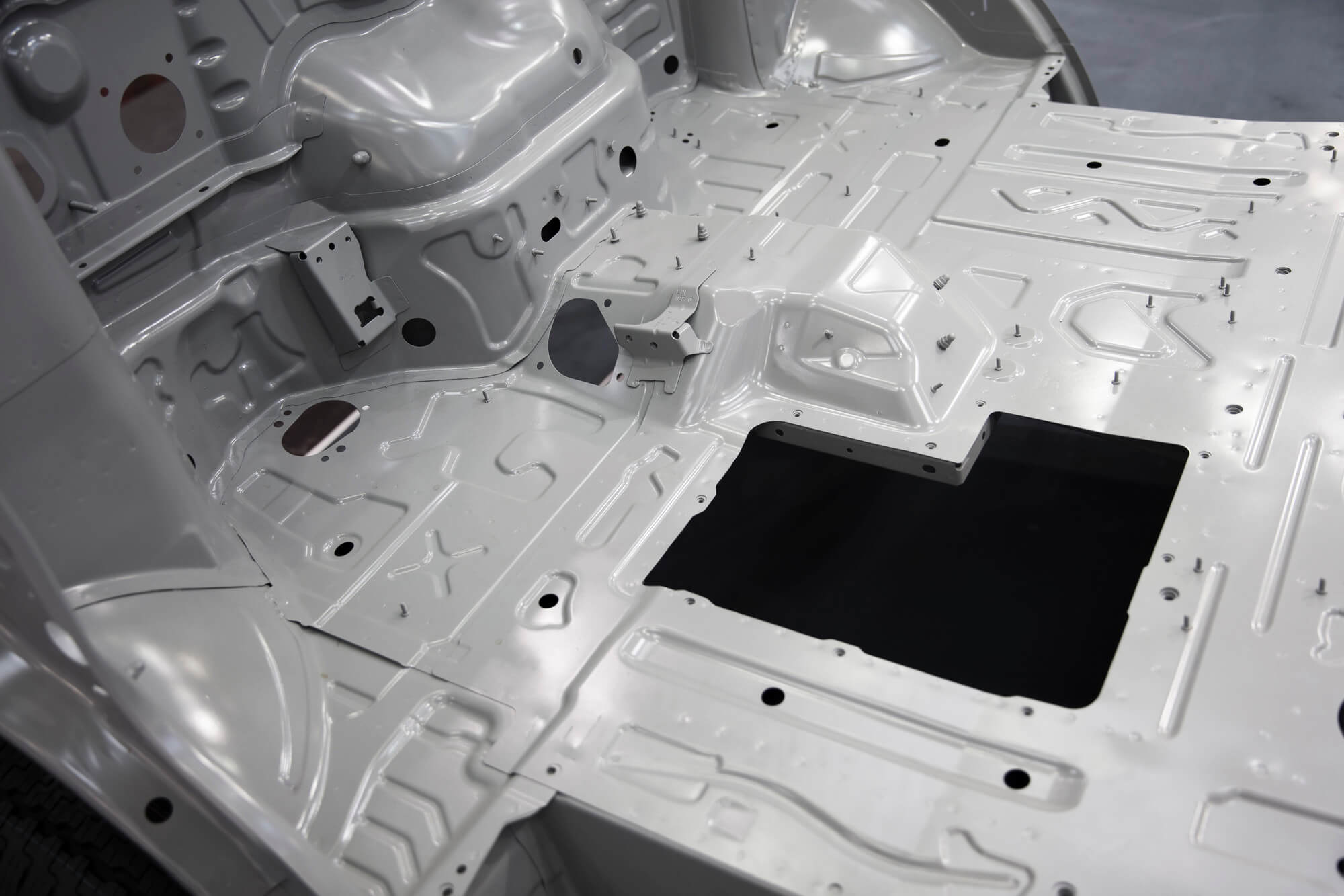
Aluminum frames are essential components in aerospace, replacing traditional assembly structures with large integral structures. These frames, such as the X3280 frame for helicopters, have significantly improved the manufacturing cycle, quality, and mechanical performance of products. However, they also bring challenges, especially when it comes to machining deformation. This deformation is largely influenced by residual stress, cutting forces, and heat generated during the machining process.
The Challenge of Machining Large Aluminum Frames
Large integral aluminum frames have significant dimensions, often reaching several meters in length and width. These structures are complex, have high precision requirements, and involve substantial cutting volumes. For instance, the X3280 frame starts from a blank weighing 550 kg and ends up as a part weighing only 10.1 kg, with a material removal rate of 98%. The thin walls and low rigidity of the final product make deformation a significant issue. In practical terms, this means that manufacturers often have to remove up to 540 kg of material, resulting in significant potential for machining-induced stresses and deformations.
Factors Contributing to Machining Deformation
Several factors contribute to machining deformation, including cutting forces, cutting heat, and residual stresses. Cutting forces cause elastic deformation in the workpiece, leading to shape and dimensional errors once the force is removed. Cutting heat can cause thermal expansion, further complicating the issue. However, residual stress, both from the material blank and induced during machining, plays a major role in the deformation of aluminum frames.
Cutting Forces
Cutting forces generated during the machining process can cause immediate elastic deformation of the workpiece. When the cutting force is removed, the elastic deformation recovers partially, causing dimensional inaccuracies. Cutting force can be minimized through optimization of cutting parameters such as feed rate and cutting speed, and by using sharp, high-quality tools.
Cutting Heat
The heat generated during the cutting process can lead to thermal expansion and subsequent contraction of the workpiece. This expansion and contraction cycle can result in thermal stresses that contribute to deformation. Effective cooling strategies, including the use of cutting fluids and controlling cutting speeds, can mitigate these thermal effects.
Understanding Residual Stress
Residual stress exists within the material blank due to previous manufacturing processes, such as rolling and heat treatment. Even after processes like vibration, artificial aging, or pre-stretching, residual stress cannot be entirely eliminated. This stress redistributes during machining, leading to deformation. For example, a pre-stretched aluminum plate, commonly used in aerospace, still retains significant residual stresses even after pre-stretching and artificial aging.
Residual Stress from Rolling and Heat Treatment
During the rolling process, aluminum plates are subjected to high levels of mechanical stress, which result in residual stresses once the rolling is completed. Heat treatment, including processes like quenching and aging, can further introduce residual stresses due to differential cooling rates between the surface and interior of the material.
Mitigation Techniques
Several techniques are employed to reduce residual stress in aluminum blanks, including:
- Vibration Stress Relief: Applying controlled vibrations to the material to help redistribute and reduce internal stresses.
- Thermal Stress Relief: Heating the material to a specific temperature and then cooling it slowly to relieve residual stresses.
- Pre-Stretching: Applying a controlled tensile force to the material to reduce internal stresses.
Finite Element Simulation of Residual Stress
To understand the impact of residual stress on machining deformation, finite element simulation is used. This method helps in predicting the deformation by simulating the release and redistribution of residual stress during the cutting process. The simulation involves creating a model of the part, applying the residual stress, and simulating the machining process.
Case Study: 7075T7351 Aluminum Alloy
In our study, we used a 7075T7351 aluminum alloy, a common material in the aerospace industry. The blank was pre-stretched to reduce residual stress, then subjected to finite element analysis to predict deformation. The material properties, such as elastic modulus (73 GPa) and Poisson’s ratio (0.33), were incorporated into the model.
Simulation Model
The finite element model was created by dividing the blank into layers, with each layer representing a portion of the material to be removed. The model included the effects of pre-stretching, simulating the initial residual stress distribution. During the simulation, material removal was performed layer by layer, mimicking the actual machining process.
Simulation and Analysis
The results showed that the residual stress release caused significant deformation, particularly in the thin-walled sections of the part. The deformation was most pronounced when about 60% of the material had been removed, after which it gradually decreased. This finding suggests that machining strategies should consider the stages at which the most significant deformation occurs to minimize errors.
Data Analysis
| Machining Stage | Material Removed (%) | Deformation (mm) |
|---|---|---|
| 1 | 10 | 0.036 |
| 2 | 20 | 0.049 |
| 3 | 30 | 0.058 |
| 4 | 40 | 0.079 |
| 5 | 50 | 0.066 |
| 6 | 60 | 0.038 |
| 7 | 70 | 0.037 |
| 8 | 80 | 0.029 |
The table above highlights how the deformation changes with different stages of material removal. As seen, the deformation peaks around the 40% removal stage and then gradually decreases.
Practical Implications and Solutions
Understanding the relationship between residual stress and machining deformation allows for better control of the process. One practical solution is to perform intermediate stress relief treatments during machining, especially after removing substantial material. Another approach is to optimize the machining sequence and parameters to balance the stress distribution.
Intermediate Stress Relief Techniques
- Vibration Stress Relief: This involves applying controlled vibrations to the part to help redistribute and reduce residual stress. It’s especially useful after significant material removal.
- Thermal Stress Relief: Heating the part to a specific temperature and then cooling it gradually can help relieve residual stresses. However, this method must be carefully controlled to avoid introducing new stresses.
Optimizing Machining Parameters
- Cutting Speed and Feed Rate: Adjusting the cutting speed and feed rate can help balance the forces on the part, reducing the risk of excessive deformation.
- Tool Path Planning: Strategically planning the tool path to ensure even material removal can help maintain balance in the part, reducing deformation.
Case Study: Machining an Aluminum Frame
Consider a case where an aluminum frame of dimensions 3000 mm x 2000 mm x 100 mm is being machined. The initial blank weighs approximately 450 kg, and the final part weighs about 20 kg. This means that about 430 kg of material must be removed. During the machining process, it’s crucial to monitor and control the deformation.
Using finite element simulation, the machining process can be planned to minimize deformation. For example, starting with rough cuts to remove large chunks of material can help distribute the residual stress. After removing about 50-60% of the material, it may be beneficial to perform an intermediate stress relief process, such as vibration stress relief, before proceeding with the final cuts.
Intermediate Stress Relief Techniques
- Vibration Stress Relief: This involves applying controlled vibrations to the part to help redistribute and reduce residual stress. It’s especially useful after significant material removal.
- Thermal Stress Relief: Heating the part to a specific temperature and then cooling it gradually can help relieve residual stresses. However, this method must be carefully controlled to avoid introducing new stresses.
Optimizing Machining Parameters
- Cutting Speed and Feed Rate: Adjusting the cutting speed and feed rate can help balance the forces on the part, reducing the risk of excessive deformation.
- Tool Path Planning: Strategically planning the tool path to ensure even material removal can help maintain balance in the part, reducing deformation.
Conclusion
Mastering the machining of large aluminum frames in CNC parts involves understanding and controlling the deformation caused by residual stress. By using finite element simulation and adopting practical machining strategies, it is possible to minimize deformation, ensuring high precision and quality in aerospace components. This approach not only improves product performance but also reduces manufacturing costs and time.
The integration of simulation with practical machining processes offers a robust solution to the challenges posed by residual stress. By anticipating and mitigating deformation, manufacturers can achieve higher accuracy and efficiency, crucial for the demanding requirements of aerospace applications.
Other Articles You Might Enjoy
- Analyzing Residual Stress in Aluminum Alloy CNC Machining Parts
Residual stress is a crucial factor affecting the performance and durability of aluminum alloy components in aerospace applications. These parts are often large, thin-walled, and complex in structure, making them…
- Overcoming Deformation Issues in CNC Machining of Aerospace Aluminum Parts
In the aerospace industry, large aluminum alloy thin-wall structures are prized for their lightweight and high-strength properties. However, machining these components presents a set of unique challenges, primarily due to…
- Simulation Analysis of Deformation in Aluminum Alloy Frame Parts during CNC Machining
Introduction Aluminum alloy frame parts are like the unsung heroes of the aerospace industry. These components, found in aircraft frames, beams, and bulkheads, are critical for ensuring structural integrity and…
- CNC Machining Materials: Acrylic vs. Polycarbonate for Transparent Components
CNC Machining: An Introduction and the Importance of Material Type Computer Numerical Control (CNC) machining is a manufacturing process where pre-programmed computer software dictates the movement of factory tools and…
- Understanding Aluminum Grades and Properties in CNC Machining (Aluminum Grades and Properties Lynn)
In the field of computer numerical control(CNC) machining, understanding aluminum grades, their properties, as well as how they influence the manufacturing process is vital. Aluminum, owing to its favorable properties…
- Aluminum Grades: Key Characteristics and CNC Machining(Aluminum Grades and Properties Gemma)
As advancements in manufacturing technologies continue to evolve, industries are leveraging more efficient methods like CNC machining for their production processes. One of the commonly used materials in these operations…


 Afrikaans
 Albanian
 Amharic
 Arabic
 Armenian
 Azerbaijani
 Basque
 Belarusian
 Bengali
 Bosnian
 Bulgarian
 Catalan
 Cebuano
 Chichewa
 Chinese (Simplified)
 Chinese (Traditional)
 Corsican
 Croatian
 Czech
Czech Danish
 Dutch
Dutch English
 Esperanto
 Estonian
 Filipino
 Finnish
 French
 Frisian
 Galician
 Georgian
 German
 Greek
Greek Gujarati
 Haitian Creole
 Hausa
Hausa Hawaiian
 Hebrew
 Hindi
Hindi Hmong
Hmong Hungarian
 Icelandic
 Igbo
Igbo Indonesian
 Irish
Irish Italian
 Japanese
 Javanese
 Kannada
 Kazakh
 Khmer
Khmer Korean
 Kurdish (Kurmanji)
 Kyrgyz
 Lao
Lao Latin
Latin Latvian
 Lithuanian
 Luxembourgish
 Macedonian
 Malagasy
 Malay
Malay Malayalam
 Maltese
 Maori
Maori Marathi
 Mongolian
 Myanmar (Burmese)
 Nepali
 Norwegian
 Pashto
 Persian
 Polish
 Portuguese
 Punjabi
 Romanian
 Russian
 Samoan
 Scottish Gaelic
 Serbian
 Sesotho
 Shona
Shona Sindhi
 Sinhala
 Slovak
 Slovenian
 Somali
 Spanish
 Sundanese
 Swahili
 Swedish
 Tajik
Tajik Tamil
Tamil Telugu
 Thai
Thai Turkish
 Ukrainian
 Urdu
Urdu Uzbek
Uzbek Vietnamese
 Welsh
Welsh Xhosa
Xhosa Yiddish
 Yoruba
 Zulu
Zulu