In CNC turning and boring operations in the world of precision machining, transitioning from shoulders to outer diameters (or vice versa) often requires corner transitions. Many engineering drawings will specify these transitions, but they don’t always provide exact dimensions. This is where the programmer steps in, typically choosing values between 0.005 to 0.020 inches (0.125 to 0.500 mm). These transitions can be either 45° chamfers or 90° radii, usually small in size. When the drawing specifies the transition size, the programmer can use it directly. These transitions serve three main practical purposes:
- Functionality: Enhancing strength, ease of assembly, and providing some clearance.
- Safety: Sharp corners can be dangerous.
- Aesthetics: The finished part looks better.
In lathe operations, corner transitions are mainly used between shoulders and adjacent outer diameters, such as on a shaft with 90° cuts. Calculating the start and end points is not difficult but can be time-consuming, especially for parts with multiple different diameters.
Let’s dive into an example with the workpiece shown in Figure 1. This piece has multiple corners, making it beneficial to use automatic corner transition programming. However, not all corners in the figure can use this method.
Figure 1:
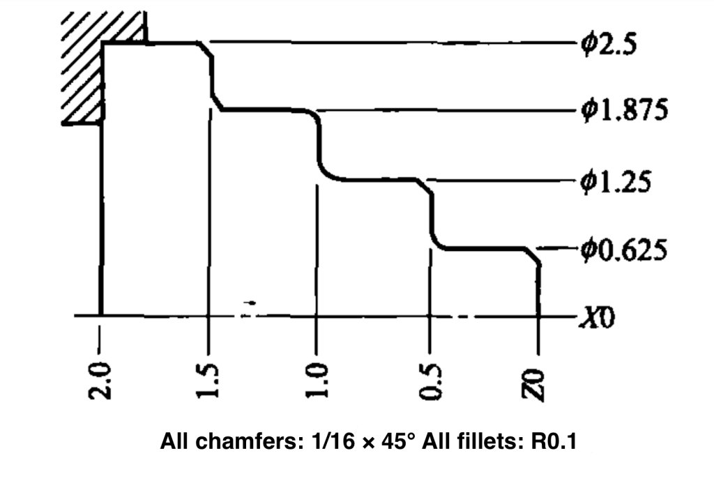
Manual Calculation vs. Automatic Corner Transitions
Manual calculation involves determining each transition point by hand, resulting in a lengthy program. Here’s an example of such a program (03404):
N51 T0100
N52 G96 S450 M03
N53 G00 G42 X0.3 Z0.1 T0101 M08
N54 G01 X0.625 Z-0.0625 F0.003
N55 Z-0.4
N56 G02 X0.825 Z-0.5 R0.1
N57 G01 X1.125
N58 X1.25 Z-0.5625
N59 Z-0.9
N60 G02 X1.45 Z-1.0 R0.1
N61 G01 X1.675
N62 G03 X1.875 Z-1.1 R0.1
N63 G01 Z-1.4375
N64 X2.0 Z-1.5
N65 X2.375
N66 X2.5 Z-1.5875
N67 U0.2
N68 G00 G40 X10.0 Z5.0 T0100
N69 M01
This program only covers finishing, starting from a selected safe distance (X0.3). Each corner transition point requires careful calculation. The key challenge is to avoid common errors like forgetting to double the X-axis values, which represent diameters.
In contrast, automatic corner transition programming simplifies this process. Using specific vectors (I, K for chamfers; R for radii), the control system automatically adjusts the toolpath length, saving time and reducing errors.
Programming Automatic Chamfers and Radii
For automatic chamfers and radii, Fanuc control systems provide two primary methods:
- 45° Chamfer: Using I and K vectors.
- 90° Radius: Using R vectors.
Automatic Chamfer (45°)
In G01 mode, the I and K vectors represent the direction and amount of the chamfer. Here’s an example program using automatic chamfers and radii (03405):
03405 (Using Automatic Corner Transitions)
N51 T0100
N52 G96 S450 M03
N53 G00 G42 X0.3 Z0.1 T0101 M08
N54 G01 X0.625 Z-0.0625 F0.003
N55 Z-0.5 R0.1
N56 X1.25 K-0.0625
N57 Z-1.0 R0.1
N58 X1.875 R-0.1
N59 Z-1.5 I0.0625
N60 X2.375
N61 X2.5 Z-1.5875
N62 U0.2
N63 G00 G40 X10.0 Z5.0 T0100
N64 M01
Compared to manual calculation, this method shortens the program and eliminates the need for manual transition point calculations. It makes program development quicker and easier, especially when dimensions need to be changed. Simply updating the vector values adjusts the transition sizes without recalculating everything.
Summary
Mastering automatic corner transitions in precision machining not only streamlines programming but also enhances the efficiency and accuracy of the machining process. By utilizing automatic chamfers and radii, programmers can reduce errors, save time, and ensure the final product meets design specifications with a high degree of precision.