Introduction
Overview of GD&T Symbols and CNC
Geometric Dimensioning and Tolerancing (GD&T) is a language used to define the geometry and tolerance of mechanical components. When working with CNC (Computer Numerical Control) machining, GD&T ensures that the parts being manufactured are within the desired tolerances and meet the required specifications for performance.In custom machining, where unique designs and tight tolerances are often required, GD&T becomes even more critical for achieving the precision necessary for high-quality results.
Imagine you’re a machinist working on a high-precision aerospace part. You need to manufacture a component where each feature must fit precisely with others, while maintaining strict tolerances to ensure the part functions flawlessly. GD&T symbols guide the machinist on how to approach these tasks. From defining the flatness of a surface to ensuring holes are in the right position relative to a datum, GD&T symbols act as the bridge between design intent and CNC execution.
In CNC machining, the application of GD&T symbols has a direct impact on machining strategies. These symbols help programmers, machinists, and engineers understand the required part geometry and how to produce parts efficiently while maintaining high precision. Understanding GD&T symbols is crucial for ensuring that parts are designed and machined correctly, without the need for costly revisions.
Why Understanding GD&T and CNC is Important
Mastering GD&T symbols is critical in CNC machining for several reasons:
- Improved Precision: CNC machines are built to execute with extreme precision. By incorporating GD&T, engineers and machinists can ensure that parts are manufactured with the exact geometry and tolerances required.
- Efficiency in Manufacturing: GD&T eliminates ambiguity in the design and machining process. Clear specifications allow machinists to work faster and more accurately, reducing the chances of mistakes, rework, or delays.
- Enhanced Quality Control: With GD&T symbols, quality control teams can easily check if parts conform to design requirements, ensuring that each part meets the necessary functional standards.
By understanding and correctly applying GD&T symbols, engineers and machinists can streamline the manufacturing process, reduce costs, and improve the final product’s performance.
What Are GD&T Symbols?
Definition of GD&T
GD&T is a symbolic language used to define the geometry of parts in engineering drawings. The symbols allow the designer to communicate how the part should be manufactured and inspected, specifying the allowable variation for each geometric feature.
This system goes beyond traditional dimensional tolerances to control things like flatness, roundness, perpendicularity, and location relative to other features. It offers precise guidance on how features must relate to each other to ensure that parts fit and function together in complex assemblies.
Key GD&T Symbols
Here are the main categories of GD&T symbols and how they impact part design and manufacturing:
Form Controls
These symbols control the form of features, ensuring they meet specific geometric requirements.
| Symbol | Name | Definition | Impact on CNC Machining |
|---|---|---|---|
| ⏣ | Flatness | Ensures a surface remains perfectly flat within a tolerance zone | Prevents warping or uneven surfaces when machining flat parts |
| ⏪ | Straightness | Ensures a line or axis is perfectly straight | Ensures precision when machining linear features like shafts |
| ⭕ | Circularity | Ensures a feature remains perfectly round | Critical for machining round holes and cylindrical features |
| ⬤ | Cylindricity | Ensures that a cylindrical feature is uniform | Important for cylindrical parts like shafts or pipes |
Orientation Controls
These symbols define how features are oriented relative to each other.
| Symbol | Name | Definition | Impact on CNC Machining |
|---|---|---|---|
| ⊥ | Perpendicularity | Ensures two features are at 90° to each other | Helps in maintaining alignment when machining features like holes on a vertical surface |
| ‖ | Parallelism | Ensures two features are parallel to each other | Crucial for parts requiring multiple aligned surfaces |
| ∠ | Angularity | Ensures two features are at a specific angle relative to each other | Used for machining angled surfaces, reducing rework |
Location Controls
These symbols define the exact location of features in 3D space.
| Symbol | Name | Definition | Impact on CNC Machining |
|---|---|---|---|
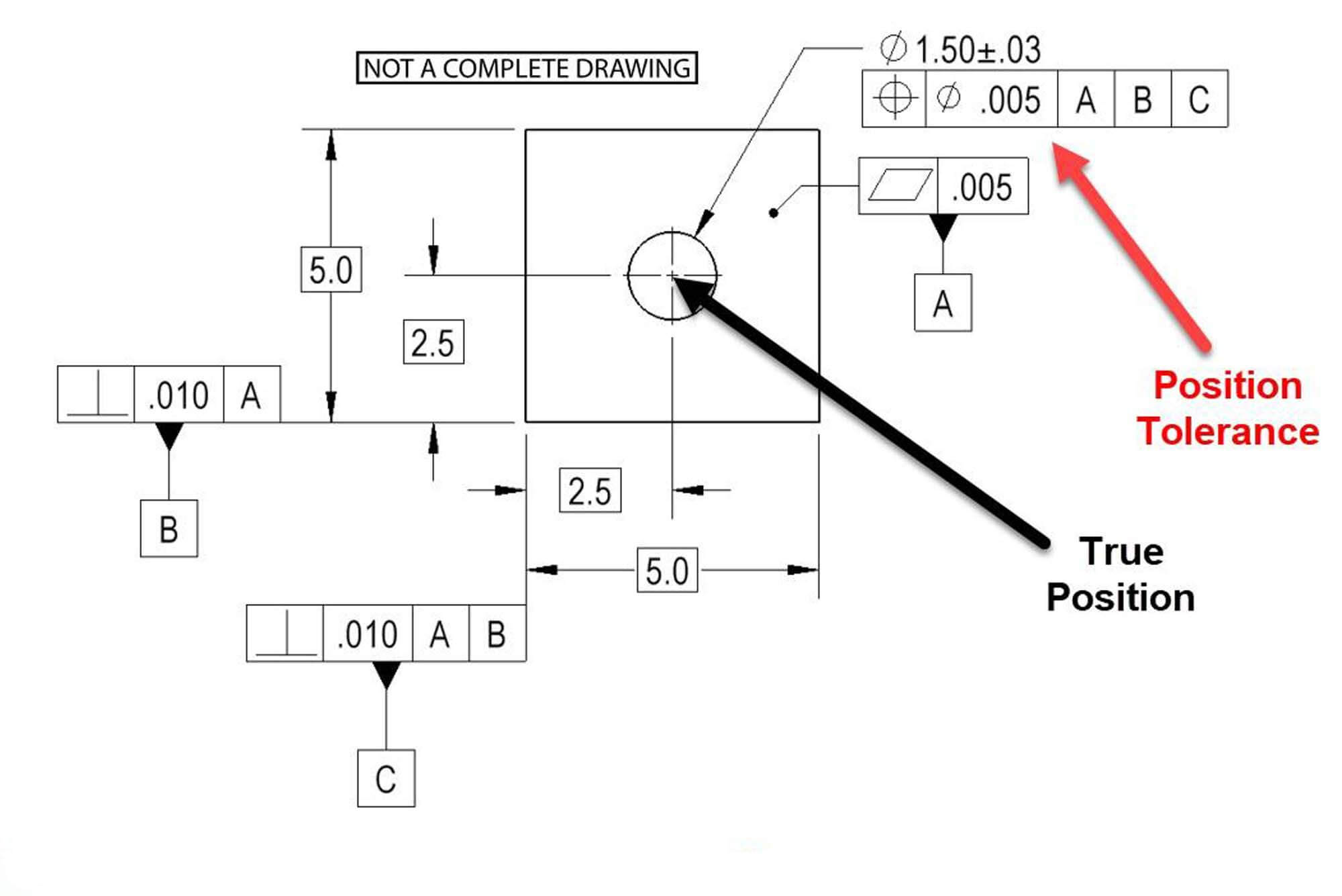
| ⊗ | Position | Specifies the exact location of a feature relative to a datum | Important for precise hole locations and complex part assembly |
| ⏺ | Concentricity | Ensures two circular features share the same centerline | Used in applications where concentric features must align, such as bushings and bearings |
| ✺ | Symmetry | Ensures features are symmetrically aligned on opposite sides | Applied to parts with symmetrical features like brackets or frames |
Runout Controls
These symbols control how much variation is allowed during the rotation of a part.
| Symbol | Name | Definition | Impact on CNC Machining |
|---|---|---|---|
| ⌀ | Circular Runout | Ensures that a rotating feature stays within a tolerance zone | Essential for parts that rotate, ensuring smooth function and reducing vibration |
| Total Runout | Total Runout | Ensures the entire surface stays within a tolerance zone | Ensures that the entire feature, not just a portion, is manufactured with accuracy |
Profile Controls
Profile controls define the exact shape of a feature or surface.
| Symbol | Name | Definition | Impact on CNC Machining |
|---|---|---|---|
| ▯ | Profile of a Surface | Defines a 3D tolerance for the surface geometry of a part | Applied to complex surfaces, such as the contours of a mold or casing |
| Profile of a Line | Profile of a Line | Specifies the tolerance for a feature along a straight line | Used for defining the accuracy of linear features like edges or seams |
How Each Symbol Affects CNC Machining
Every GD&T symbol impacts the machining process by defining how a specific feature should be created and inspected. For example:
- Flatness ensures a flat surface, which could affect tool choice and how the workpiece is clamped in the CNC machine.
- Circularity affects how round a hole should be, influencing the precision of the cutting tool and the setup for drilling or turning operations.
- Perpendicularity and Parallelism require careful machine alignment and setup to ensure features maintain their relationships with each other.
Understanding these symbols helps machinists and CNC programmers select the right tools, calibrate the machines correctly, and ensure that parts are manufactured within the acceptable tolerances.
How GD&T Symbols Impact CNC Machining
The Role of GD&T in CNC Programming
In CNC programming, GD&T symbols play a pivotal role. When programming a CNC machine, the machinist must interpret the GD&T symbols to decide on:
- Tool paths: The path the machine tool follows is influenced by the GD&T requirements. For example, if a part feature needs to be perfectly round, the tool path must ensure circularity.
- Cutting strategies: Depending on the GD&T tolerances, the program may need to adjust cutting speeds, feed rates, and tool engagement to meet the specified form control.
- Machine settings: GD&T symbols dictate how the machine is set up and calibrated. For example, setting the machine to ensure perpendicularity between surfaces requires adjusting the machine’s alignment.
Machining Tolerances and Their Importance
GD&T symbols directly affect the tolerances that are applied to the machining process. Tolerances define the acceptable variation in a part’s dimensions and are crucial for ensuring the part fits and functions as intended.
For example:
- Position tolerance specifies how far a hole can deviate from its exact position, which is critical for assembly purposes.
- Straightness tolerance ensures that features like edges or shafts are perfectly straight, which is essential for parts that need to be assembled or rotate without wobbling.
Understanding and applying GD&T ensures that parts are made to the exact specifications needed for functional assembly.
Understanding GD&T in CNC: Step-by-Step
Step 1: Read the Engineering Drawing
The first step in any CNC machining process that involves GD&T symbols is to thoroughly understand the engineering drawing. These drawings are like the blueprint for the entire machining process and contain crucial information regarding GD&T.
How to Interpret GD&T Symbols:
- Each GD&T symbol corresponds to a specific geometric characteristic or tolerance. For example, a circle with a diagonal line through it ( ⭕ ) represents Circularity, indicating the feature must be round to within a specified tolerance.
- Most drawings will also have a Datum indicated, which is a reference point or surface from which other measurements are taken. This datum is essential for accurately applying GD&T symbols.
- Common mistakes to avoid:
- Misinterpreting the tolerance value: Ensure the tolerance value is properly understood to avoid producing parts out of spec.
- Skipping over the datums: Datums are critical in ensuring the parts are manufactured with correct orientation and position.
Best Practices:
- Use GD&T charts and standards (such as ASME Y14.5) to ensure you’re interpreting the symbols correctly.
- Pay attention to the relationship between different features (such as position or concentricity) to understand how the parts will fit together.
Step 2: Translate GD&T into CNC Program Code
Once the drawing is understood, the next step is translating the GD&T symbols into CNC programming code. This is where CNC programmers need to translate the geometry and tolerances into machine commands.
For example, if the drawing calls for flatness ( ⏣ ), the CNC program should include commands for tool paths that ensure the surface is machined flat within the tolerance.
Key Considerations in CNC Programming:
- Coordinate Systems: Properly define the datums in the CNC program to ensure that the part features are manufactured according to the engineering drawing.
- Machine Setup: CNC machines must be calibrated to ensure that they can meet the GD&T tolerances, especially when working with tight tolerances like circularity or perpendicularity.
- Tooling: Select tools that are capable of achieving the required tolerance. For example, high-precision tools might be required for cylindricity or angularity.
Step 3: Setting Up CNC Machines for GD&T
Once the program is ready, it’s time to set up the CNC machine. Proper machine setup ensures the features will be manufactured according to the GD&T specifications.
Key Setup Steps:
- Tool Selection: Ensure the correct tools are chosen based on the features described by the GD&T symbols. For example, tools for circularity require specific rounding cutters, while perpendicularity may need the machine to be precisely aligned.
- Calibration: Machines need to be calibrated to ensure they can meet the precise tolerances specified by the GD&T symbols. Use laser calibration tools or precision jigs to ensure the CNC machine is aligned properly.
Step 4: Quality Control and GD&T Compliance
The final step in the process is quality control. After machining, the parts need to be inspected to ensure they conform to the GD&T specifications.
Quality Control Tools:
- Coordinate Measuring Machines (CMMs): These are used to measure the part dimensions and check if they meet the required GD&T tolerances. CMMs can measure flatness, position, and other geometric tolerances with high precision.
- Optical Scanners: Optical scanners can measure the surface profile of the part, ensuring that features like flatness and profile of a surface are within specification.
- Laser Scanning: Laser scanning is another useful tool to measure part accuracy and check for compliance with GD&T symbols.
Benefits of Using GD&T with CNC Machining
Increased Precision and Accuracy
One of the most significant benefits of using GD&T symbols in CNC machining is the increased precision and accuracy of the final product. By setting clear tolerances, you can ensure that parts are manufactured within the required geometric specifications.
For example, using GD&T symbols such as position ensures that features like holes are positioned accurately in relation to each other and the datums, leading to improved fit and function in assemblies.
Faster Turnaround Times
By using GD&T symbols, CNC programmers can streamline the machining process, reducing the time spent on setting up machines and inspecting parts. For example, using GD&T symbols to define circularity and roundness allows the machinist to use automated machines that adjust cutting paths dynamically, saving time and improving efficiency.
Improved Quality Control
Since GD&T symbols are specific and measurable, they greatly improve the quality control process. Clear tolerances reduce ambiguity in inspection, enabling easier verification of part conformity.
Using tools like CMMs and laser scanners, quality control teams can quickly and accurately check parts for compliance with GD&T specifications, reducing the chance of defects and rework.
Lower Production Costs
Efficient machining based on GD&T results in lower production costs by minimizing errors, reducing material waste, and improving first-time success rates. GD&T ensures that parts are manufactured correctly the first time, which leads to fewer rejected parts and reduced scrap.
Tools and Technologies for CNC Machining with GD&T
CAD/CAM Software
CAD/CAM software such as SolidWorks, AutoCAD, and Mastercam is used to design parts and prepare the CNC program. These software tools allow engineers to incorporate GD&T symbols directly into the design, making it easier to program the CNC machine and ensure the correct machining processes are applied.
- SolidWorks allows for integrating GD&T directly into part designs, ensuring that all manufacturing constraints are clear.
- Mastercam is widely used for CNC programming and offers tools for generating machine code that incorporates GD&T tolerances.
CNC Machine Tools
CNC machine tools such as milling machines, turning centers, and grinding machines are used to machine parts according to the GD&T specifications. The precision of these machines is essential in ensuring that parts meet the tolerances defined by GD&T symbols.
- Milling machines are used for making flat and contoured parts that require flatness, profile of a surface, or perpendicularity.
- Turning centers are used for cylindrical parts, ensuring circularity, cylindricity, and runout tolerances.
Inspection Tools for GD&T
Once parts are machined, tools like CMMs and optical scanners are used to inspect the parts.
- CMMs provide 3D measurements and can check various GD&T symbols, including position, flatness, and angularity.
- Optical scanners are used to measure the surface profile, ensuring that features like circularity and profile of a surface are within specification.
Common Mistakes When Using GD&T in CNC
Misunderstanding Symbol Meanings
One of the most common mistakes when using GD&T in CNC machining is misinterpreting the meaning of the symbols. For example, position tolerance controls the location of features, but it is often misunderstood as controlling the feature’s size.
Inaccurate Machine Calibration
Improper machine calibration can lead to inaccurate machining results. When working with GD&T, especially tight tolerances, ensuring the CNC machine is properly calibrated is crucial.
Incorrect Use of Tolerances
Using tolerances incorrectly or unnecessarily complicating the design with overly strict tolerances can increase machining time and cost. It’s important to balance precision with practicality.
Overcomplicating Design
Designing parts with unnecessary GD&T symbols can make the manufacturing process more complex than it needs to be. Understanding when to apply GD&T symbols and when to use simpler tolerances is key to maintaining an efficient machining process.
Future Trends in GD&T and CNC
Automation and GD&T
With the rise of automated manufacturing systems, GD&T is becoming even more integrated into the production process. CNC machines with built-in capabilities for GD&T allow for faster, more accurate machining with fewer manual adjustments.
Digital Twin and GD&T
The use of digital twins is emerging in manufacturing. A digital twin is a virtual model of a physical part or system, allowing for real-time monitoring and modification of the machining process to ensure compliance with GD&Tspecifications.
Sustainability and GD&T
By reducing material waste and increasing part yield, GD&T can contribute to sustainability in manufacturing. Parts that are precisely machined using GD&T tolerances require less rework and result in less scrap material.
FAQ
- What are GD&T symbols used for?
- GD&T symbols are used to define part geometry and tolerances, ensuring that parts are manufactured to precise specifications.
- Why is GD&T important in CNC machining?
- GD&T improves machining accuracy, speeds up production cycles, and ensures parts fit together properly during assembly.
- What is the difference between GD&T and traditional tolerancing methods?
- Traditional tolerancing is less precise, while GD&T offers a more standardized system that clearly defines geometric tolerances and their relationships.
- How do you read GD&T symbols on an engineering drawing?
- GD&T symbols are located near the feature they apply to and describe the geometric tolerance for that feature.
- What does the position symbol mean in GD&T?
- The position symbol controls the location of features relative to datums.
- How can CNC programmers integrate GD&T symbols into machine code?
- CNC programmers can use CAD/CAM software to convert GD&T symbols into CNC machine commands.
- What are the challenges of machining parts with tight GD&T tolerances?
- Tight tolerances can cause machining errors, misalignment, and increased production time.
- Can GD&T symbols affect the selection of CNC tools?
- Yes, specific tools are required to meet the tolerances defined by GD&T symbols, such as precision cutters for roundness or flatness.
- How does GD&T improve the overall quality control process in manufacturing?
- GD&T provides measurable tolerances, making it easier to verify whether parts conform to design specifications.
- What software tools are used to implement GD&T in CNC machining?
- Software tools like SolidWorks, AutoCAD, and Mastercam allow engineers and CNC programmers to integrate GD&T symbols into their designs and programs.
- How do I measure a part’s GD&T compliance using CMM?
- Coordinate Measuring Machines (CMMs) measure part dimensions and check them against the specified GD&T tolerances.
- What is the profile of a surface symbol in GD&T?
- This symbol defines the tolerance for the surface’s profile, ensuring it meets specific geometric requirements.
- What are common mistakes when using GD&T in CNC machining?
- Common mistakes include misinterpreting symbols, incorrect machine calibration, and overcomplicating the design.
- How does GD&T help in reducing production costs?
- By reducing errors and ensuring parts meet specifications the first time, GD&T lowers scrap rates and improves efficiency.
- What is the future of GD&T in CNC machining with automation?
- Automation in CNC machining, paired with GD&T, is leading to faster, more accurate production, with fewer manual interventions.
Other Articles You Might Enjoy
- Mastering stl to gcode: A Complete Guide for 3D Printing and CNC Enthusiasts
Chapter 1. Introduction I remember the first time I tried converting stl to gcode for a simple 3D printing project.I thought it would be as straightforward as clicking a button.But…
- Machining Techniques for Parts: Unlocking CNC and Cutting-Edge Tech
I. Introduction I remember the first time I realized how critical machining is to modern manufacturing. I was interning at a small shop, watching a CNC machine carve intricate features…
- Choosing the Right CMM Machine for Your Production Needs
When it comes to precision measurement in manufacturing, CMM machines (Coordinate Measuring Machines) have become indispensable. Selecting the right CMM machine for your specific production needs can be quite challenging,…
- Precision Machining: Crafting the Future of High-Tolerance Manufacturing
Why Precision Machining Matters in Modern Manufacturing Precision machining is a cornerstone of modern manufacturing. It enables the creation of complex, high-tolerance parts used across a wide range of industries.…
- CNC Precision Machining High-Temperature Alloys for Heavy-Duty Vehicle Parts
1. Introduction In the automotive, aerospace, and maritime industries, high-temperature alloys have become vital materials for manufacturing components that must withstand extreme temperatures and stress. CNC precision machining has emerged…
- Nickel vs. Cobalt Alloys in High-Temperature CNC Machining: A Detailed Analysis?
Nickel and Cobalt Alloys in High-Temperature CNC Machining Both Nickel and Cobalt alloys play an essential role in high-temperature CNC machining. These metal alloys are popular choices due to their…
- Mastering Corner Control in CNC Machining Parts
CNC machining is all about precision and efficiency, especially when it comes to navigating sharp corners and changing directions. When machining complex contours, the feed rate and movement control are…
- Applications and Advantages of Bronze CNC Machining
1. Introduction: The Enduring Allure of Bronze in CNC Machining In this opening section, we explore the timeless appeal of bronze as a material for CNC machining. From its rich…


