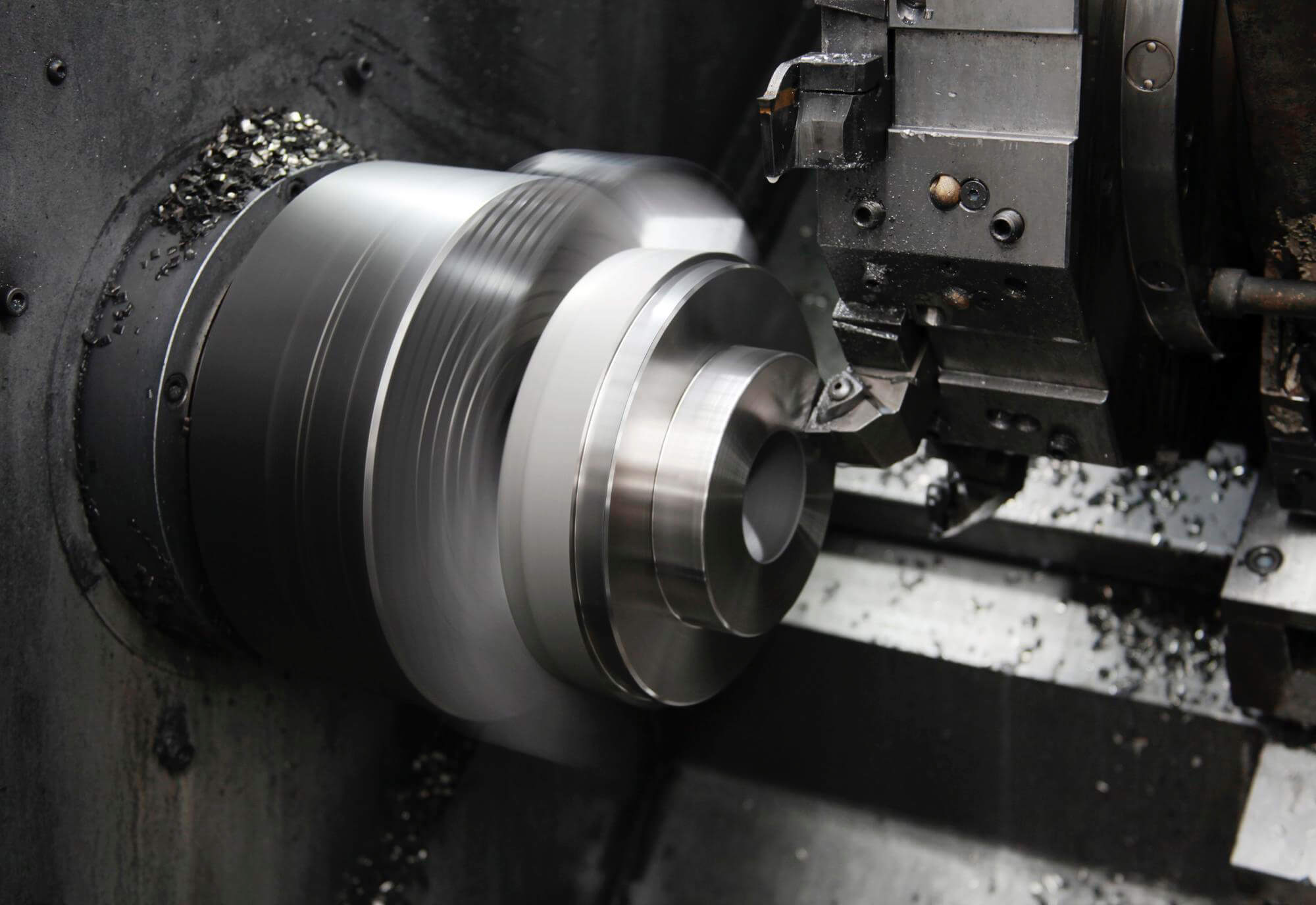
Thread tapping is one of the most common hole machining operations on CNC machining centers, right after drilling. Due to its widespread application in many milling operations, most control systems offer two thread tapping cycles for programming: the most common G84 right-hand thread tapping cycle (R/H) and the G74 left-hand thread tapping cycle (L/H).
Understanding G84 and G74 Cycles
G84 is the standard tapping cycle used for right-hand threads, where the spindle rotates using M03 with a right-hand tap. On the other hand, G74 is used for left-hand threads, with the spindle rotating using M04 with a left-hand tap.
Here’s an example of a tapping program, illustrating how the tapping operation is programmed similar to other fixed cycles. The fixed cycle includes all tool movements, along with spindle stops and reversals at the bottom of the hole:
N64 G90 G54 G00 X3.5 Y7.125 S600 M03 T06
N65 G43 Z1.0 H05 M08
N66 G99 G84 R0.4 Z-0.84 F30.0
N67 G80
Can you determine the tap size used in this program? Though not explicitly mentioned, it provides enough information for a skilled CNC operator to deduce the details. This example uses a standard 20 TPI (threads per inch) tap. The crucial value here is the feed rate of 30.0 inches per minute (in/min), which is carefully calculated based on the spindle speed (S).
Calculating Feed Rate for Tapping
The feed rate for any tapping operation must synchronize with the spindle speed. Since a tap is a forming tool, its thread size and shape are determined by the tap itself. Here’s how you calculate the feed rate:
F = 1 / TPI * S
F = 1 / 20 * 600 = 30.0 in/min
Alternatively, you can divide the spindle speed by the number of threads per inch:
F = S / TPI
F = 600 / 20 = 30.0 in/min
Factors Influencing Tapping Quality
Several factors affect the overall quality of a tapped hole, including the material, coating, geometry of the tap, spiral flute, helix angle, chamfer type, cutting material, and tool holder. Unless your CNC machine supports rigid tapping, it’s advisable to use a floating tap holder. This design gives the tap a “feel” similar to manual tapping, allowing it to float within a certain range. Rigid tapping is common on modern CNC machines and does not require special tap holders, reducing tooling costs. However, it’s essential to ensure that the CNC machine and its controller support this function.
Geometry of Taps
The design of taps significantly impacts programming and data input values. Two critical aspects are the tap’s spiral flute and chamfer geometry.
- Spiral Flute Geometry: Taps come in various designs described in tool catalogs as “low spiral,” “high spiral,” “straight flute,” etc. The efficiency of the spiral flute depends on the spindle speed, tap lead (pitch), and material being tapped.
- Chamfer Geometry: The chamfer geometry is crucial for proper hole machining and varies depending on whether you’re machining a blind hole or a through hole.
Taps can be categorized into taper taps, plug taps, and bottoming taps, each with different chamfer lengths and angles.
Programming Tapping Cycles on CNC Lathes
Thread tapping on CNC lathes is similar to tapping on machining centers, though without fixed cycles (except in mill-turn mode). Lathes use the G32 command for segmental tapping motion programming. Ensure correct tap alignment, spindle speed, and feed rate for accurate results.
Pipe Taps
Pipe taps, similar to standard taps, are divided into two groups: tapered threads (NPT or API) and straight (parallel) threads (NPS). Their nominal size corresponds to the fitting size rather than the actual thread size. The taper of NPT pipe taps is 1:16, with a chamfer of 2-3 threads.
When programming pipe taps, calculating the Z-depth to a reasonable value is crucial, and experiments may be necessary for exact results. Below is a table with NPT pipe tap sizes and recommended tap drills to assist in CNC programming:
| NPT Group | Tap Drill (in) | Small Tap Drill (in) |
|---|---|---|
| 1/16 | 0.2460 | 15/64 |
| 1/8 | 0.3320 | 21/64 |
| 1/4 | 0.4375 | 27/64 |
| 3/8 | 37/64 | 9/16 |
| 1/2 | 45/64 | 11/16 |
| 3/4 | 29/32 | 57/64 |
| 1.0 | 1-9/64 | 1-1/8 |
| 1-1/4 | 1-31/64 | 1-15/32 |
| 1-1/2 | 1-47/64 | 1-23/32 |
| 2.0 | 2-13/64 | 2-3/16 |
For straight pipe taps (NPS), use the following table:
| Pipe Tap Size | TPI | Tap Drill (in) |
|---|---|---|
| 1/16 | 27 | 1/4 |
| 1/8 | 27 | 11/32 |
| 1/4 | 18 | 7/16 |
| 3/8 | 18 | 37/64 |
| 1/2 | 14 | 23/32 |
| 3/4 | 14 | 59/64 |
| 1.0 | 11-1/2 | 1-5/32 |
| 1-1/4 | 11-1/2 | 1-1/2 |
| 1-1/2 | 11-1/2 | 1-3/4 |
| 2.0 | 11-1/2 | 2-7/32 |
Checklist for Tapping Operations
When programming tapping operations, ensure the following data accurately reflect the machining conditions. These values might vary across setups and machines but remain consistent in most CNC machines and tapping operations:
- Sharp and correctly mounted tap cutting edges
- Tap design matching the hole being machined
- Proper tap alignment with the hole
- Appropriate spindle speed and feed rate
- Correct workpiece setup
- Proper pre-machining of the hole (drill size matters)
- Adequate clearance for the starting position (for acceleration)
- Suitable cutting fluid
- Sufficient bottom clearance in blind holes
- Adjustable torque on the tap holder (for easier cutting)
- Complete and error-free program
Many tap holders have unique requirements that might influence programming methods. If unsure, refer to the tap holder manufacturer’s recommendations.
With modern CNC machines, rigid tapping is quite common. It doesn’t require specialized tap holders, only standard end mill holders or collets, thereby reducing tooling costs. However, always verify if the CNC machine supports rigid tapping mode before programming.
Other Articles You Might Enjoy
- Mastering Corner Control in CNC Machining Parts
CNC machining is all about precision and efficiency, especially when it comes to navigating sharp corners and changing directions. When machining complex contours, the feed rate and movement control are…
- Nickel vs. Cobalt Alloys in High-Temperature CNC Machining: A Detailed Analysis?
Nickel and Cobalt Alloys in High-Temperature CNC Machining Both Nickel and Cobalt alloys play an essential role in high-temperature CNC machining. These metal alloys are popular choices due to their…
- Requirements for CNC Machining Parts
Preparation Work Complete the necessary preparation before machining, including process analysis, process route design, tool and fixture selection, and program compilation. online cnc machining service Operating Steps and Contents Start…
- Tapping Methods in CNC Machining
Classification and Characteristics of Tapping in CNC Machining Tapping, using taps to machine threaded holes, is the most commonly used method for creating threaded holes. It is mainly suitable for…
- Mastering the Craft of Bead Blasting in CNC Machining(cnc machining tools Bblythe)
In the dynamic world of computer numerical control (CNC) machining, bead blasting is a pivotal process that contributes significantly to the quality and appearance of machined products. It's frequently used…
- Mastering Bead Blasting in CNC Machining(cnc g code Malcolm)
Bead blasting is a critical operation within the context of Computer Numerical Control (CNC) machining, which demands precision and excellence. As an intricate technique, bead blasting carries substantial importance for…