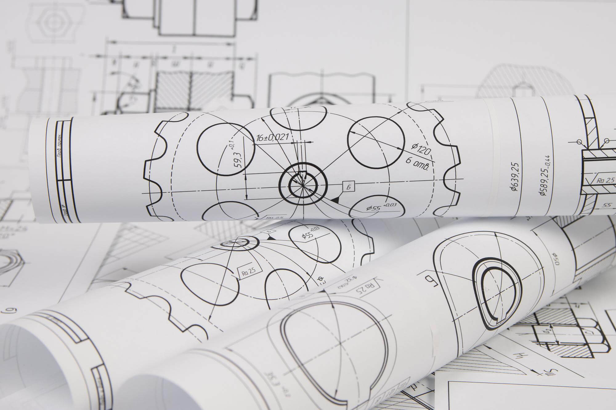
In mechanical processing, drawing annotations play a crucial role. The first key point is that the true size of the part should be based on the dimensions indicated on the drawing, rather than the size of the graphics or the accuracy of the drawing. The dimensions marked on the drawing are usually in millimeters, and if other units are used, they must be clearly indicated.
For example, if the drawing specifies a dimension of 45°30′, it should be clearly stated in the notes that this is an angular measurement. If this dimension is the final finished size, it should also be indicated on the drawing.
Common Dimension Annotation Symbols and Abbreviations
In mechanical drawing, commonly used dimension annotation symbols and abbreviations are varied. The table below lists some common dimension symbols and their abbreviations:
| Name | Symbol or Abbreviation |
|---|---|
| Diameter | φ |
| Radius | R |
| Sphere Diameter | Sφ |
| Thickness | t |
| Square | □ |
| 45° Chamfer | C |
| Equally Spaced | EQS |
| Arc Length | ⌒ |
| Countersink | ∨ |
These symbols not only make annotations more concise on the drawing but also prevent misunderstandings. For instance, seeing “φ” indicates a diameter annotation, avoiding confusion with other dimensions.
Basic Principles of Dimension Annotation
The four fundamental principles of dimension annotation are correctness, completeness, clarity, and reasonableness. Here are some specific considerations:
- True Size as Basis: The actual size of the object should be based on the dimensions indicated on the drawing, regardless of the size of the graphic.
- Measurement Units: Dimensions on the drawing are in millimeters by default. If other units are used, they must be specified.
- Single Annotation per Dimension: Each dimension is generally annotated only once on the drawing and should be indicated on the graphic that best reflects the structure.
- Final Dimensions: The dimensions indicated on the drawing are the final finished dimensions unless otherwise specified.
Common Errors and Improvements in Dimension Annotation
Common issues in mechanical drawing dimensions include:
- Incomplete, cluttered, missing, or duplicate annotations: Important dimensions on parts must be directly marked to avoid closed dimensions and to facilitate processing and measurement.
- High precision requirements without tolerance annotations: This can lead to significant processing errors, potentially resulting in part rejection.
- Non-standard technical requirement annotations: This includes dimensions, shape, position tolerances, and surface roughness annotations.
Components and Methods of Dimension Annotation
A complete dimension annotation should include dimension lines, extension lines, terminators, and dimension numbers. Here are the definitions and requirements:
- Extension Lines: Indicate the range of dimensions, drawn with thin solid lines, extending from the outline, axis, or symmetry centerlines.
- Dimension Lines: Indicate the direction of the dimension measurement, drawn with thin solid lines, and must not be replaced with other lines or overlap with other lines.
- Dimension Numbers: Indicate the actual size of the object, usually marked above or in the middle of the dimension line, and must not be crossed by any other line.
Contents and Requirements for Part Drawings
A complete part drawing includes graphics, complete dimensions, technical requirements, and a title block. The title block should include the part name, material, quantity, scale, drawing number, and signatures of the design, drafting, and review personnel. Here are some specific requirements:
- View Representation: Use a set of views to represent the internal and external structural shapes of the part.
- Dimension Annotation: Correctly, completely, clearly, and reasonably annotate all dimensions required for manufacturing, inspection, and assembly.
- Technical Requirements: Specify the requirements needed during processing, inspection, and assembly.
Dimension Tolerances and Surface Roughness
Dimension Tolerances are the allowable variations in dimension sizes, critical for manufacturing precision. Tolerance zones are determined by upper and lower deviations, and the tolerance zone code consists of the basic deviation code and tolerance grade. Surface Roughness is an important indicator of the surface quality of parts, commonly evaluated by parameters like Ra, Rz, and Ry.
Below is a simple table example describing different Ra values corresponding to processing methods:
| Ra Value (μm) | Processing Method | Application Example |
|---|---|---|
| 50 – 25 | Rough turning, milling, planing | Base surfaces, shaft ends, chamfers |
| 12.5 – 6.3 | Drilling, sawing | Non-working surfaces of keyways, castings |
| 6.3 – 3.2 | Fine turning, fine milling | Working surfaces of keyways, shaft ends, locating pins |
| 3.2 – 1.6 | Fine planing, reaming | Working surfaces of gears, important surfaces of bearings |
| 1.6 – 0.8 | Precision grinding, polishing | High-precision fitting surfaces, sealing surfaces |
Other Articles You Might Enjoy
- Common Materials and Processability of Mechanical Parts
Mechanical parts are indispensable components in various machines and equipment. To ensure these parts operate efficiently under different working conditions, it is essential to understand the common materials used for…
- Requirements for CNC Machining Parts
Preparation Work Complete the necessary preparation before machining, including process analysis, process route design, tool and fixture selection, and program compilation. online cnc machining service Operating Steps and Contents Start…
- What are the requirements for CNC machining of bearing parts?
Bearings are common and important parts in the automotive industry, which can support transmission components and transmit torque. Generally, CNC machining centers are used to process bearing parts. So what…
- Tapping Methods in CNC Machining
Classification and Characteristics of Tapping in CNC Machining Tapping, using taps to machine threaded holes, is the most commonly used method for creating threaded holes. It is mainly suitable for…
- Title: Galvanized Steel: Process, Methods, Properties, and Uses
Introduction: Galvanized steel, an innovation in the world of construction and manufacturing, represents a pinnacle in material engineering. It's a process where steel is coated with a protective layer of…
- Interrupt Methods in CNC Machining: Key to Ensuring Safety and Efficiency
In the dynamic world of CNC machining, the ability to safely and efficiently interrupt a machining process is crucial. There are several methods available to operators to pause or stop…


