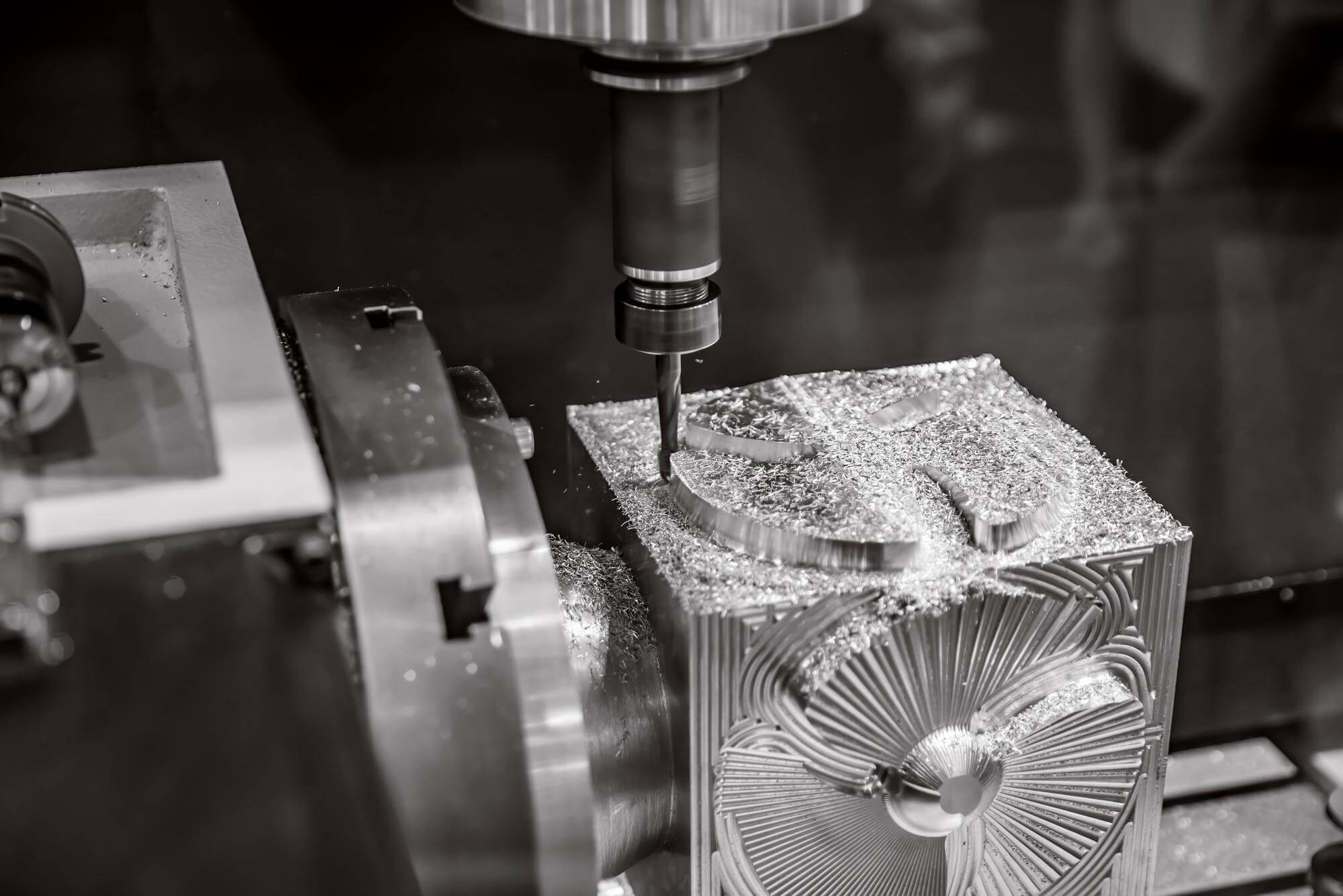
Mechanical machining surface quality is a crucial aspect of mechanical manufacturing that directly impacts the performance and longevity of parts. This article will discuss the principles, influencing factors, and practical applications of mechanical machining surface quality to help readers better understand and apply this knowledge.
Principles of Mechanical Machining Surface Quality
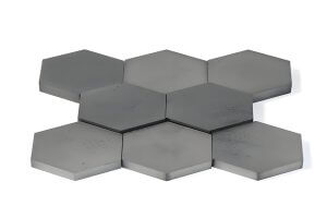
Mechanical machining surface quality refers to the micro-roughness of the surface of a part after machining, also known as roughness. Roughness is denoted by Ra, Rz, and Ry, each followed by numerical values. For instance, when the surface roughness Ra < 0.8μm, it is referred to as a “mirror surface.”
The mirror surface is the ideal state of metal cutting processing, significantly enhancing the service life of mechanical components. Regardless of the metal processing method used, fine irregular tool marks will always be left on the surface of parts, creating a crisscross pattern of peaks and valleys. This was previously referred to as surface smoothness.
There are two types of methods to achieve a mirror surface: material removal methods and non-cutting methods (rolling processing).
- Material Removal Methods: Grinding, lapping, polishing, electrical discharge machining (EDM).
- Non-Cutting Methods: Rolling (using mirror tools), extrusion.
Concept of Surface Roughness
Surface roughness refers to the micro-geometric shape characteristics composed of small spacing and peak-valley on the processing surface. It is an important issue in the study of interchangeability. Surface roughness is generally formed by the processing method and other factors, such as friction between the tool and the part surface during processing, plastic deformation of the surface metal when the chips are separated, and high-frequency vibration in the process system.
Surface Roughness Classification and Processing Methods Table
| Surface Feature | Surface Roughness (Ra) Value | Example Processing Methods |
|---|---|---|
| Clearly visible tool marks | Ra100, Ra50, Ra25 | Rough turning, rough planing, rough milling, drilling |
| Slightly visible tool marks | Ra12.5, Ra6.3, Ra3.2 | Fine turning, fine planing, fine milling, rough reaming, rough grinding |
| No visible processing marks, slightly distinguishable direction | Ra1.6, Ra0.8, Ra0.4 | Fine turning, fine grinding, fine reaming, lapping |
| Matte surface | Ra0.2, Ra0.1, Ra0.05 | Lapping, honing, superfinishing, polishing |
Causes of Surface Roughness
The main causes of surface roughness include:
- Tool Marks During Processing: Marks left by the tool during processing.
- Plastic Deformation During Chip Separation: Metal undergoes plastic deformation during cutting, leading to an uneven surface.
- Friction Between Tool and Processed Surface: Friction causes fine bumps on the surface.
- High-Frequency Vibration in the Process System: Vibration leaves irregular marks on the surface.
Impact of Surface Roughness
Surface roughness affects the performance of parts in several ways:
- Wear Resistance: The rougher the surface, the smaller the contact area, and the faster the wear.
- Stability of Fit Properties: Rough surfaces are prone to wear, reducing the stability of fit.
- Fatigue Strength: Large valleys on rough surfaces act like sharp notches and cracks, reducing fatigue strength.
- Corrosion Resistance: Rough surfaces easily accumulate corrosive substances, leading to corrosion.
- Sealing Performance: Rough surfaces cannot fit tightly, causing leakage of gases or liquids.
- Contact Stiffness: Rough surfaces reduce contact stiffness, affecting the rigidity of parts.
- Measurement Accuracy: Surface roughness affects the precision of measurement tools.
Examples:
- Automotive Engine Blocks: High surface quality improves wear resistance and sealing performance, extending the engine’s service life.
- Aerospace Components: High surface quality improves fatigue resistance, ensuring flight safety.
Selection of Surface Roughness
The selection of surface roughness parameter values should meet the functional requirements of the part’s surface while considering economic rationality. When selecting, one can refer to existing similar part drawings and use the analogy method to determine. The parameter value should be as large as possible to reduce processing costs while meeting the functional requirements of the part.
Practical Advice:
- For working surfaces, mating surfaces, and sealing surfaces, choose smaller surface roughness parameter values to ensure performance and reliability.
- For non-working surfaces and low-precision surfaces, choose larger surface roughness parameter values to reduce processing costs.
Measures to Reduce Surface Roughness
- Select Reasonable Cutting Parameters: Cutting speed significantly affects surface roughness. High-speed cutting or reduced cutting speeds typically result in smaller roughness values as built-up edges are less likely to form. Adjusting feed rate and depth of cut also helps in reducing surface roughness.
- Choose Appropriate Tool Geometry: Increasing the rake angle and clearance angle helps in reducing surface roughness. A larger rake angle decreases plastic deformation and cutting force, reducing vibrations and improving surface quality.
- Use Suitable Cutting Fluids and Tool Materials: Cutting fluids provide lubrication and cooling, which helps in reducing surface roughness. The tool’s surface finish and hardness also significantly impact the roughness of the workpiece.
Representation of Surface Roughness (GB—T131—1993)
Surface roughness symbols consist of the surface roughness symbol itself and the numerical values and related symbols around it.
- The drawing method of the surface roughness symbol, as shown in the figure, selects the size of the symbol according to the regulations.
- The numerical value and related regulations of the roughness are marked on the surface roughness symbol. When using the surface roughness parameter value Ra, omit the symbol Ra and write only its value above the surface roughness symbol, in micrometers (μm).
- If it is necessary to indicate sampling length, specified processing methods, coating, or other surface treatment requirements, or control the processing texture direction, it must be marked in the symbol.
Methods of Measuring Surface Roughness
- Comparison Method: Using surface roughness comparison blocks, visually and tactually compare with the measured surface to determine the corresponding roughness value.
- Stylus Method: A diamond stylus with a curvature radius of about 2 microns moves slowly along the measured surface. The vertical displacement of the stylus is converted into an electrical signal, displaying the surface roughness value.
- Light Section Method: A light beam projected through a slit onto the measured surface creates a sectional contour, which is measured using a microscope and micrometer drum.
- Interference Method: Utilizing light wave interference principles to display the surface shape errors, and measuring the microscopic parts of the interference fringes with a high-magnification microscope to determine surface roughness.
Differences Between Surface Roughness and Surface Finish
Surface roughness is measured based on the actual micro-geometric shape of the surface, whereas surface finish is a qualitative measure based on human perception. To align with international standards, China adopted surface roughness and discontinued the term surface finish in the 1980s.
By understanding the principles of surface roughness, measurement methods, measures to reduce roughness, and influencing factors, appropriate processing methods and parameters can be chosen to improve the surface quality of parts.
Other Articles You Might Enjoy
- The Role of Ceramic Beads in Achieving Superior Surface Quality in CNC Machining
Introduction to Ceramic Beads in CNC Machining Ceramic beads, known for their hardness and spherical uniformity, have emerged as a pivotal component in CNC machining operations aimed at achieving superior…
- Surface Refinement: Leveraging Bead Blasting for CNC Machining
In the realm of CNC machining, surface quality plays a pivotal role in determining the overall performance and aesthetics of the final product. Leveraging bead blasting as a surface refinement…
- The Dependable Quality Assurance in China CNC Machining
1. Introduction: Setting the Stage for Quality Excellence In this introductory section, we lay the groundwork for an exploration into the world of quality assurance in China CNC machining. We…
- How to solve surface roughness problems in cnc machining?
Introduction to CNC Machining and Surface Roughness Problems The process of Computer Numerical Control (CNC) machining plays a vital role in the manufacturing industry. This automated process uses computers to…
- Bead Blasting: The Secret to Quality CNC Machining(cnc machining tools Mavis)
The world of manufacturing has witnessed revolutionary changes with the advent of Computer Numerical Control (CNC) machining. It is a process used in the manufacturing sector that involves the use…
- Zinc Alloys in CNC Machining: Benefits and Limitations
Introduction - CNC Machining and Zinc Alloys Computer Numerical Control (CNC) machining is a highly precise manufacturing process widely utilized in various industries to create complex parts. It makes use…