I. Introduction: What Is a Pinion Bearing and Why CNC Matters
When I first started designing mechanical assemblies, I often heard people talk about a “pinion bearing.” It seemed like everyone I knew in automotive and industrial sectors used this phrase. But I realized that many folks, including me back then, didn’t fully understand the difference between a regular bearing and a pinion bearing.
In this first chapter, I’ll lay out the basics: the definition of a pinion bearing, where it’s used, why precision is crucial, and how CNC machining fits into the picture.
1. Definition of a Pinion Bearing
A pinion bearing is a specialized bearing designed to support the shaft that carries a pinion gear. Pinion gears typically mesh with larger ring gears or planetary gear sets in gearboxes, differentials, or other mechanical transmissions. Since the pinion gear is often a primary input or output, the bearing around it has to control both radial and axial movement.
When I first encountered the term pinion bearing, I assumed it was just another standard roller or ball bearing. But as I dug deeper, I realized the pinion bearing must handle unique stress profiles. It’s not just about simple rotation; it’s also about transmitting significant torque and maintaining precise gear mesh.
2. Typical Applications
From my experience, pinion bearing assemblies appear in several industries. The most common is automotive, where a pinion gear drives or is driven by a ring gear in a differential or gearbox. The bearing ensures the pinion stays aligned under varying loads, preventing noise or premature wear.
In aerospace, pinion bearings might support turbine shafts or actuator drives. Precision and weight-saving measures matter greatly here, so advanced materials and tight tolerances are the norm.
I’ve also come across pinion bearings in wind turbines, where the gear systems handle massive torque. Lastly, robotics is another sector that uses small pinion gears to transfer motion and torque efficiently, often requiring miniature yet high-precision bearings.
3. Why Precision Matters in Pinion Bearings
I learned quickly that misalignment or excessive play in a pinion bearing can be disastrous. Gear noise, tooth wear, and reduced efficiency can result if the gear mesh isn’t stable. For high-speed or high-torque applications, small deviations can escalate into major mechanical failures.
Precision ensures smooth gear engagement and longer component life. From what I’ve seen, a difference of just a few microns in bearing diameter or runout can create noticeable vibrations. This is especially true in automotive differentials, where drivers often complain about whine or clunking if the pinion bearing isn’t holding the gear in perfect alignment.
4. Role of CNC Machining in Producing High-Tolerance Bearings
Modern CNC machining excels at producing components to incredibly tight tolerances. When manufacturing a pinion bearing, CNC processes like turning, grinding, and multi-axis milling enable us to achieve precise dimensions.
I’ve worked on projects where we needed a bearing race with less than 0.001 inches of total runout. Achieving that by hand or with older manual methods would be a huge challenge. However, CNC can maintain consistent tolerances across multiple parts, essential for mass production.
CNC also streamlines prototyping. We can modify the design of a pinion bearing in CAD, then quickly machine a new iteration without extensive retooling. This flexibility is invaluable when designing custom or high-performance gear systems.
II. Understanding Pinion Bearings: Function, Load Types, and Design
1. Difference Between a Pinion Bearing and a Regular Bearing
A pinion bearing supports the shaft that carries a pinion gear.
In many gear systems, that pinion gear meshes with a ring gear or other gear sets to transmit torque.
A regular bearing might focus on reducing friction for a rotating shaft, but a pinion bearing must also ensure precise gear alignment.
Some bearings only manage radial loads.
Others only handle axial loads.
A pinion bearing typically deals with both.
It prevents the pinion gear from shifting under heavy torque or sudden directional changes.
I’ve seen cases where a generic bearing allowed excessive play, causing gear teeth to rattle under load.
That rattle led to premature wear and unwanted vibration.
A pinion bearing often features tapered rollers or an equivalent design.
This geometry accommodates multidirectional forces without adding too much friction.
In contrast, a common ball bearing might struggle with substantial axial thrust.
The pinion bearing also requires meticulous preload control.
Preload is the slight internal force that ensures the rolling elements stay in solid contact with the raceways.
If preload is too loose, the gear can wobble.
If it’s too tight, heat and friction climb, risking early failure.
I once replaced a standard roller bearing in a small differential with a specialized pinion bearing.
The difference was immediate.
Gear noise dropped, and the system felt smoother under acceleration.
2. Common Design Types (Roller, Tapered, Needle)
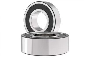
Roller Bearings
Roller bearings use cylindrical rollers between an inner and outer race.
They excel at handling radial loads.
Some versions can manage limited axial forces, though they usually need a separate thrust bearing if axial loads become significant.
Roller bearings are a straightforward upgrade over basic ball bearings when you expect heavier radial stress.
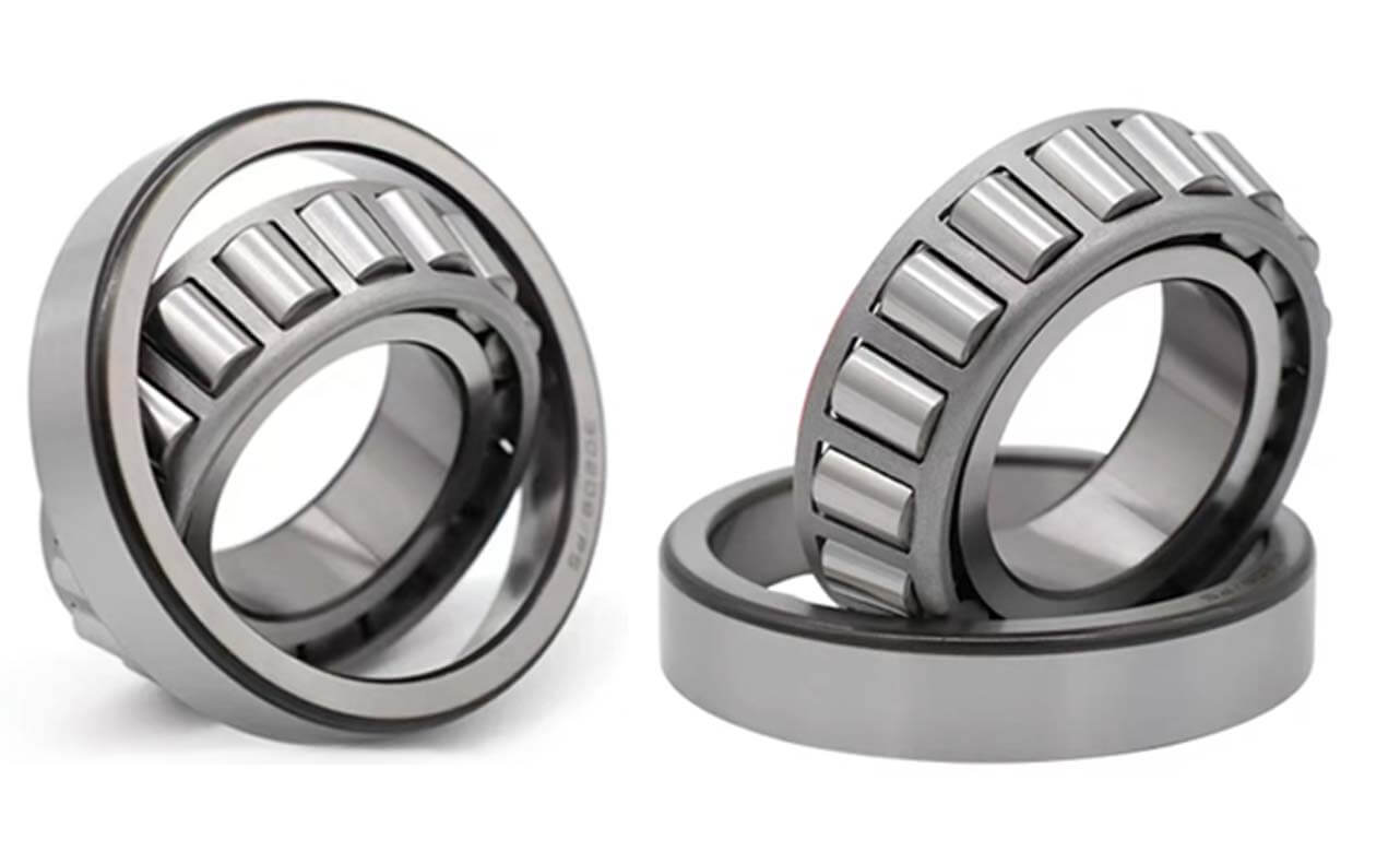
Tapered Roller Bearings
Tapered roller bearings handle both radial and axial loads.
Their rollers are conical, allowing them to distribute force along a tapered surface.
In a pinion bearing application, they’re popular because they stabilize the shaft from multiple directions.
During my first automotive project, I discovered that tapered roller bearings held the pinion gear rigidly, preventing gear chatter.
That rigidity is crucial for smooth gear meshing at high speed.
Needle Bearings
Needle bearings feature thin, elongated rollers.
They fit into tight spaces and support moderate radial loads.
However, their axial load capacity is limited without additional components.
They’re occasionally found in smaller or lighter-duty pinion systems.
In high-torque applications, though, a purely needle-based design may not suffice.
Hybrid Designs
Some gearboxes employ combinations, like a tapered roller on one side and a needle or roller bearing on the other.
This mix can optimize space, weight, and cost.
When a system demands strong thrust support on one end but modest radial support on the other, hybrid setups make sense.
3. Radial vs Axial Loads in Gear Systems
A pinion gear experiences both radial and axial forces as it meshes with another gear.
Radial loads push the gear sideways, while axial loads push it along its shaft’s length.
The exact distribution depends on gear geometry.
Spur gears mostly create radial loads, whereas helical or bevel gears add more axial thrust.
If a bearing can’t handle the full load spectrum, the shaft can shift.
That shift leads to uneven tooth contact, raising the chance of pitting or scoring on the gear faces.
Radial Loads
Radial loads act perpendicular to the shaft axis.
They tend to push or pull the pinion gear away from the ring gear’s center.
If this load isn’t well-supported by the pinion bearing, gear teeth can separate or bind.
Axial Loads
Axial loads push along the shaft’s length.
In a hypoid or helical gear arrangement, this thrust can be significant.
A well-chosen pinion bearing ensures the gear stays in alignment.
I recall a spiral bevel gearbox where we saw excessive gear wear because the bearing wasn’t rated for the heavy axial load.
4. Bearing Materials and Heat Treatment
Many pinion bearings are made from steels like 52100 or other high-carbon alloys.
These materials offer good hardness and wear resistance when heat-treated correctly.
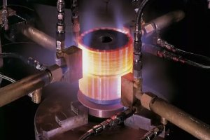
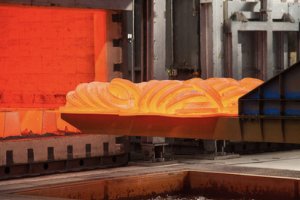
Heat treatment involves controlled heating, quenching, and tempering steps that define final hardness and toughness.
I’ve seen how a poor heat treatment process can ruin a batch of pinion bearings.
Uneven hardness leads to unexpected stress concentrations.
That can cause spalling, where tiny fragments break off the bearing surface under load.
Spalling shows up as rough patches on the raceways or rollers.
Common Materials
- 52100 Steel (GCr15): Classic bearing steel, known for toughness and fatigue life.
- Stainless Steel (440C): Offers corrosion resistance but can be more brittle.
- Alloy Steels (e.g., 4140): Good balance of strength and machinability.
- Carburizing Steels: Core remains tough, while the surface becomes very hard.
Heat Treatment Stages
- Austenitizing: Heating steel to a temperature where its crystal structure transforms.
- Quenching: Rapid cooling in oil, water, or polymer to lock in a harder structure.
- Tempering: Reheating at a lower temperature to reduce brittleness and relieve internal stresses.
The final hardness is often measured on the Rockwell C scale, with typical values between HRC 58 and 65 for bearing components.
That level can vary with the brand or application.
Surface Treatments and Coatings
Some pinion bearings receive coatings like titanium nitride or diamond-like carbon.
These reduce friction and increase surface hardness.
I once tried a coated bearing for a high-speed gear train, and it showed reduced friction and lower operating temperature.
The added cost was justified by longer service life.
Data Table: Bearing Materials and Typical Heat Treatment
Below is a table comparing common materials and their usual heat treatment profiles for pinion bearing production:
| Material | Typical Composition | Hardness Range (HRC) | Heat Treatment Steps | Pros | Cons | Example Applications |
|---|---|---|---|---|---|---|
| 52100 Steel | ~1.0% C, 1.5% Cr | 58–65 | Quench & Temper (Oil/Polymer) | High wear resistance, widely used | Can be brittle if overheated | Automotive, General Gearbox |
| 440C Stainless | ~1.0% C, 17% Cr | 56–60 | Quench & Temper (Oil or Air) | Corrosion resistant, moderate wear | Lower toughness than 52100 | Aerospace, Food Machinery |
| 4140 Alloy | ~0.4% C, 1% Cr, Mo | 45–55 (typical) | Q&T or Carburize | Good strength, machinability | Not as hard as dedicated bearing steel | Industrial Gear Systems |
| Carburizing Steel | 0.1–0.2% C, Cr, Ni | Case: 58–62, Core: ~35 | Carburize, Quench & Temper | Tough core, hard surface | Complex process, higher cost | Heavy Duty Differentials |
| M50 Tool Steel | ~0.80% C, 4.25% Mo | 60–65 | Vacuum Heat Treatment | High-temp strength, less friction | Expensive, specialized | Turbine Shafts, Aerospace |
| Titanium Alloys | Varying, e.g. 6Al-4V | ~35–40 (hardening limited) | Solution Treat & Age | Lightweight, corrosion resistant | Not always suitable for extreme loads | Specialty, Weight-Sensitive |
| Ceramic Hybrids | Steel Races, Ceramic Rollers | Races: ~60, Rollers: N/A | Standard for Steel + Sintering for Ceramics | Low friction, high speed | Very costly, limited shock tolerance | High-Speed or Precision Gear |
This table covers some typical steels and treatments used for bearings.
Certain advanced alloys or ceramics might require custom processes.
Summary of Chapter II
A pinion bearing differs from a regular bearing by its need to handle combined radial and axial loads while preserving gear alignment.
Common designs include roller bearings, tapered roller bearings, and needle bearings, each chosen based on load direction, size constraints, and torque requirements.
Pinion gears face forces from multiple angles, so the bearing’s geometry and preload become critical.
Material choice and heat treatment also influence how well the bearing endures repeated stress.
Faulty heat treatment or an improper material pick can lead to sudden failures like spalling or pitting.
Pinion bearings must endure constant rotation, sometimes at high speed, sometimes with massive torque.
Their performance hinges on precise tolerances and the ability to maintain a stable gear mesh.
In the next chapter, the focus shifts to the CNC machining processes that shape these bearings into tight tolerance components.
III. CNC Machining of Pinion Bearings: Process & Techniques
1. Suitable CNC Methods: Turning, Grinding, Multi-Axis Milling
A pinion bearing demands tight tolerances and precise geometry.
CNC turning often acts as the first operation.
It shapes the basic cylindrical forms of bearing races or housings.
I’ve seen many shops start with bar stock or a forged blank.
The workpiece rotates, while a stationary cutting tool removes excess material.
Turning is effective for large diameters and consistent radial features.
Operators can machine shoulders, grooves, or recesses where bearing rollers will rest.
If I need an inner race and outer race, I might produce both on the same CNC lathe in separate runs.
Grinding refines the work turned on the lathe.
It removes small amounts of material, honing surfaces to the desired finish.
In pinion bearing production, grinding can happen on inner diameters (ID) or outer diameters (OD).
That creates smooth raceways and maintains uniform thickness around the bearing.
Some shops use multi-axis milling for complex bearing housings.
A standard 3-axis mill can shape flat mounting flanges, bolt holes, or lubrication channels.
A 5-axis setup might handle angled surfaces, ensuring perfect alignment with the bearing’s rolling elements.
I recall a custom gearbox housing that required a five-axis approach because of its slanted oil passages.
2. Surface Finish, Roundness, Runout, and Tolerances
A pinion bearing performs best when friction is minimized.
Friction often arises from rough surfaces or poor alignment.
Surface finish directly affects how rollers or balls move inside the bearing.
Most bearing manufacturers aim for a surface roughness in the range of Ra 0.2–0.8 µm on critical contact surfaces.
Roundness measures how close a cross-section is to a perfect circle.
If a bearing’s raceway isn’t sufficiently round, rolling elements can bind or loosen.
I’ve worked on projects where a small out-of-round condition caused noise under load.
That led to gear chatter and premature bearing wear.
Runout describes how much the bearing’s rotating axis deviates from true center.
Even if the part is nominally round, slight eccentricities can cause the bore or outer diameter to wobble.
In high-speed pinion gear drives, runout can lead to uneven tooth contact.
That can create vibration, turning into gear whine or resonance.
Tolerances define how much variation is allowed in diameter, thickness, or form.
Some industries follow ISO or DIN standards, assigning tolerance grades.
Tighter tolerances usually mean a higher manufacturing cost.
But for a critical pinion bearing, the payoff is smoother operation and longer life.
3. Tooling and Fixture Design
Tool selection affects both productivity and final quality.
Hard alloys like 52100 steel require robust cutting tools, often carbide inserts.
If the bearing is already heat-treated, ceramic or cBN (cubic boron nitride) tooling might be necessary.
I remember a batch where we tried standard carbide on hardened races.
The tools wore out quickly, leading to dimensional drift halfway through the run.
Fixtures hold the workpiece securely during machining.
In CNC turning, a three-jaw or four-jaw chuck can work if it evenly distributes clamping force.
For thin rings like bearing races, special collets or expanding mandrels are often used.
An expanding mandrel pushes outward against the bore, maintaining a round shape.
Milling might call for custom clamps that secure irregular shapes.
I’ve seen setups where we used soft jaws to conform to a bearing housing’s curved exterior.
A secure fixture prevents vibration and helps the tool cut consistently.
When the fixture is poorly designed, the part can slip or distort under load.
Coolant strategy is part of fixture design.
Proper coolant nozzles remove heat and chips, keeping the part stable.
Temperatures in the cutting zone can spike if coolant flow is inadequate.
Heat causes expansion, altering precision.
4. Micro-CNC or Swiss-Type Machining for Miniature Bearings
Some pinion bearings are extremely small.
Robotics, drones, or advanced sensors may use miniature gears.
Those require equally tiny bearings, with bores under a few millimeters.
Micro-CNC machines help produce these miniature parts.
They have high-speed spindles and tight motion control.
The biggest challenge is measuring the final part accurately.
Conventional gauges might be too large or imprecise for bores that small.
Swiss-type lathes feed bar stock through a guide bushing.
The cutting tool works close to the bushing, minimizing deflection on slender parts.
For a tiny pinion shaft, a Swiss lathe can create the precise diameter needed.
I’ve seen needle bearings that fit on micro shafts turned by Swiss machines.
A single scratch or burr on a tiny race can cause functional problems.
That’s why these small bearings undergo extra inspection steps.
Sometimes we use optical measuring systems to verify geometry.
Ensuring All Factors Align
CNC methods, surface quality, tooling design, and even machine choice all influence how the final pinion bearing performs.
I’ve had scenarios where a shop nailed the turning and grinding steps but overlooked fixture stability.
The part ended up with minor ovality, leading to gear noise in a test rig.
Attention to detail at every step reduces such risks.
IV. Common Industries & Use Cases
1. Automotive (Differential Gears, Gearboxes)
The automotive sector relies heavily on a stable pinion bearing.
Inside a rear differential, a pinion gear meshes with a ring gear to transfer power to the wheels.
Any misalignment causes noise, heat buildup, and premature wear.
In front-wheel-drive setups, the pinion bearing can also be part of the transaxle, combining gearbox and differential functions in a single assembly.
Performance cars often use heavier preloads on the pinion bearing.
This increases rigidity and ensures precise gear contact.
Some tuners go so far as to install custom-bearing kits.
These kits have tighter tolerances and stronger materials.
The goal is to reduce gear lash and maintain smooth power delivery under hard acceleration.
Modern automatic transmissions include multiple gearsets.
They sometimes incorporate a small pinion bearing to support planetary gear carriers.
Those bearings operate under high rotational speeds.
They must handle quick gear shifts, torque spikes, and temperature swings.
I’ve seen sporty coupes with transmissions that spin a pinion shaft past 8,000 RPM.
Electric vehicle drivetrains use unique gear ratios.
They still require a sturdy pinion bearing for any reduction gear or differential arrangement.
High torque at low RPM can stress bearings.
A robust design helps the system withstand repeated launches or uphill driving without gear whine.
2. Aerospace (Small Turbines, Actuator Gears)
Aerospace often demands lightweight yet strong components.
Pinion bearings appear in turbine engines, actuators, and auxiliary gearboxes.
In a jet engine’s gearbox, small pinion gears drive accessories like hydraulic pumps or electric generators.
The bearing must hold alignment through rapid temperature shifts and vibrations.
Weight reduction matters in aircraft.
Engineers might choose advanced alloys or even hybrid ceramic bearings to shave off ounces.
I’ve been part of a project where we used titanium bearing housings.
That cut weight by 15% but required specialized CNC and finishing steps.
Actuators, such as those found in flight control surfaces, can also rely on a pinion bearing.
These systems convert rotary motion to linear movement.
A small, high-torque motor drives a pinion gear that interacts with racks or gear segments.
A bearing supports the pinion shaft so it can respond instantly to control commands.
Space applications can push bearings to extremes.
In satellites, temperature swings in orbit are huge.
Pinion bearings must function when the environment is frigid or scorching.
Lubrication can be tricky in a vacuum.
Some designs use dry-film lubricants or sealed cartridges.
3. Renewable Energy (Wind Turbine Gear Units)
Wind turbines have massive gearboxes.
They often use a high-speed shaft from the turbine blades that then steps down to a lower-speed generator.
A pinion gear might link an intermediate shaft to a larger bull gear.
If the pinion bearing fails, the entire gearbox can suffer catastrophic damage.
Turbines operate for long periods in harsh conditions.
Offshore farms face corrosion from salt spray.
Onshore sites endure dust, cold, or high humidity.
A pinion bearing must handle these factors while supporting significant torque.
Even small misalignments can magnify over many rotations.
Some wind turbines integrate condition monitoring.
Sensors track vibration, temperature, and noise within the gearbox.
If the pinion bearing shows signs of wear or alignment shift, the system alerts operators.
These predictive maintenance strategies help avoid unplanned downtime.
I once visited a wind farm where a main gearbox had failed.
Investigations pointed to a faulty pinion bearing preload.
Because the preload was off, the gear mesh wore unevenly.
Repairs took weeks and cost a fortune.
4. Robotics and Automation Systems
Robotics often involves smaller gears with fast, precise movements.
A pinion bearing can be part of a servo or stepper motor assembly.
It’s critical that the gear axis remains stable to allow repeatable motion.
If a joint arm’s gears slip by even fractions of a millimeter, the robot can miss its target.
In industrial automation, gearboxes might appear in conveyor drives or pick-and-place machines.
A pinion bearing can carry moderate loads but must maintain strict positioning.
Some advanced robots even use harmonic drives, though classic spur or helical gearboxes remain common.
Collaborative robots (cobots) might incorporate lightweight gearing solutions.
Those solutions still rely on a well-made pinion bearing.
Noise and backlash are huge concerns in these environments.
I’ve seen cobots that needed near-silent operation for lab use, so each bearing had a superfinished raceway.
Miniature robotics, like drones, also place demands on bearings.
High-speed motors driving pinion gears need bearings that resist vibration.
Tiny mechanical assemblies can’t afford even slight misalignment.
Hence, micro-CNC or Swiss-type turning often factors in.
5. Maintenance, Repair, and Overhaul (MRO) Services
Pinion bearings wear over time.
MRO services often replace these bearings in everything from commercial trucks to wind turbines.
Sometimes, an OEM bearing is no longer available.
That forces shops to fabricate or reverse-engineer a custom pinion bearing using CNC processes.
I’ve helped design a reverse-engineering workflow.
It involves scanning the old part, measuring wear patterns, and replicating key dimensions in CAD.
We then produce a fresh bearing using modern steels and finishing methods.
The result can exceed the original’s performance.
In older heavy machinery, a pinion bearing might be integral to the gear train.
If that bearing fails, the owner faces a dilemma: scrap the machine or find a specialty rebuilder.
Custom CNC manufacturing offers a lifeline, letting MRO shops save equipment from obsolescence.
Data Table: Examples of Pinion Bearing Use Cases
Below is a table that illustrating major use cases, loads, and other specifics for pinion bearings in various industries.
| Industry | Application | Load Characteristics | Bearing Type(s) | Key Challenge | Typical Lifecycle | Notable Trend |
|---|---|---|---|---|---|---|
| Automotive | Differential Pinion | High torque, variable speed | Tapered Roller | Maintaining tight gear mesh under load | 100k+ miles | Lighter materials |
| Aerospace | Engine Accessory Gearbox | Rapid temp swings, high RPM | Hybrid Ceramic or Steel | Must minimize weight & handle vibration | Thousands of flight hours | Exotic alloys, coatings |
| Wind Energy | Turbine Gear Units | Massive torque, slow speed | Tapered or Cylindrical | Extreme loads, harsh environments | 20+ years design target | Online condition monitoring |
| Robotics | Servo Gearboxes | Medium torque, fast response | Needle or Tapered | Precision alignment, minimal backlash | Varies (3–10 yrs) | Miniaturization |
| Industrial Mfg. | Conveyor Drives | Steady torque, moderate speed | Cylindrical or Tapered | Continuous operation demands durability | 24/7 operation possible | Smart sensors, IoT |
| Marine | Propulsion Gear Sets | Corrosive environment, vibrations | Stainless or Coated Steel | Saltwater corrosion, heavy shock loads | 10–15 yrs, major overhauls | Advanced surface treatments |
| Electric Vehicles | Reduction Gear / Transaxle | High torque from standstill | Tapered Roller, Hybrid | Sudden torque spikes, extended warranties | 100k+ miles / multi-year battery life | Thermal management |
| Legacy Machinery | Replacement / Retrofits | Varies widely, older designs | Custom CNC solutions | Parts discontinued, unknown specs | Can restore indefinite use | Reverse engineering |
This table reflects broad trends.
Specific load values, bearing types, or lifespans can shift depending on design nuances.
Chapter IV Summary
Pinion bearings appear everywhere from car differentials to wind turbines.
Each environment imposes unique stress.
Automotive applications see frequent speed changes, while wind turbines face continuous slow rotations.
Aerospace demands lightweight and vibration resistance.
Robotics emphasizes minimal backlash.
Maintenance and repair operations often rely on custom pinion bearing solutions.
Failure of one bearing can halt entire systems.
As these industries evolve, so do the materials and coatings.
Condition monitoring and advanced engineering aim to prolong bearing life.
V. Design & Manufacturing Considerations
1. Tolerances: ISO/DIN Standards
Pinion bearings follow international guidelines like ISO 492 or DIN 620.
These standards specify dimensional tolerances, runout limits, and bearing seat geometry.
When I design or inspect a pinion bearing, I refer to these benchmarks to ensure compatibility with other components.
Some classes demand extremely tight tolerances.
An ISO P4 or P2 bearing might have runout measured in microns.
Achieving that with manual machines is tough.
Modern CNC turning and grinding help us meet these standards repeatedly.
Production lines often rely on statistical process control (SPC).
We measure certain dimensions for each batch of bearings, plotting them on control charts.
If measurements drift, we correct the CNC offsets.
This approach keeps us within the required tolerance bands.
2. Lubrication Design and Surface Coatings
Bearings need lubrication to minimize metal-on-metal contact.
A pinion bearing can use grease, oil, or even solid lubricants.
In an automotive differential, splash-lubricated oil baths keep everything coated.
In enclosed gearboxes, pressurized oil jets may be directed at the bearing.
Some designs include special channels or grooves in the bearing housing.
These channels guide lubrication to the contact area.
I worked on a racing differential that used an oil pump to spray the pinion bearing.
The bearing stayed cooler under prolonged high-speed driving.
Surface coatings cut friction and protect against corrosion.
Phosphate coatings or black oxide can reduce scuffing.
Hard chromium or tungsten carbide coatings raise surface hardness.
A single scratch can become a stress riser, so protective layers help.
In high-temp environments, advanced options like titanium nitride or diamond-like carbon (DLC) might appear.
These coatings reduce friction dramatically but add cost.
I recall an aerospace actuator that used DLC-coated pinion bearings to survive repeated stress at high altitude.
3. CNC Programming Tips for Bearing Grooves and Races
CNC programming must accommodate the geometry of bearing races.
Tapered races require careful toolpath planning.
If the feed rate is too high, chatter can form on the tapered surface, hurting surface finish.
A smoother feed with stable spindle speed often yields better results.
Multi-axis machines let programmers use contour milling.
This method can generate complex bearing seats or lubrication grooves.
For grooves, I like to define a shallow trochoidal path to avoid plunging the cutter directly.
Trochoidal moves keep the tool load consistent, preventing sudden torque spikes.
Tool wear compensation is critical.
As inserts wear, they slightly alter the final dimension.
Bearing tolerances don’t allow for big deviations.
Shop-floor operators might run test cuts or measure pilot pieces, updating offsets mid-batch.
In some setups, we pass the part to a separate grinding cell.
The CNC grinder polishes the race to final specs.
That workflow merges the precision of grinding with the flexibility of turning or milling.
4. Prototyping vs Mass Production
Prototyping pinion bearings often involves smaller batches.
We might run one or two sets, tweak the design, and retest.
Development teams watch for friction, noise, or durability issues.
During prototyping, I focus on verifying the load capacity.
I also look at installation fit, ensuring the bearing seats correctly with minimal press or slip.
Once a design is proven, it may scale to mass production.
High-volume lines use automated part handling.
A robotic arm can load blanks into a CNC lathe, then pass them to a grinding station.
Smart sensors monitor tool wear, and a central system tracks part quality in real time.
This speeds up output while retaining precision.
Some shops specialize in custom, short-run orders.
They handle unique bearing sizes or exotic materials.
Others churn out thousands of standard bearings daily, relying on streamlined CNC cycles.
5. Reverse Engineering Legacy Bearings
Legacy equipment often includes a pinion bearing no longer produced by the original manufacturer.
The bearing may have outdated dimensions or an obscure part number.
Shops can reverse-engineer the old part by measuring its critical features, scanning worn surfaces, and testing material hardness.
CAD software recreates the design, adjusting for wear or known weaknesses.
Next, we choose modern steel or coatings.
Then CNC machines replicate the geometry.
I’ve seen improved variants with slightly thicker races for better load handling.
Reverse engineering can save owners from scrapping entire machines.
Mines or factories might have pricey gear drives that run well except for a single discontinued bearing.
A custom CNC approach extends the machine’s life by years.
Chapter V Summary
Designing and manufacturing a pinion bearing involves careful adherence to standards, lubrication planning, and meticulous CNC programming.
Tolerances often match international benchmarks.
Surface treatments and advanced coatings reduce friction and extend service life.
Prototyping allows teams to refine designs, while mass production harnesses automation.
Reverse engineering provides a lifeline for obsolete machinery, giving new life to old systems.
A pinion bearing is not just another rolling element.
Its form, finish, and internal geometry must match the gear train’s demands.
When designers pair robust materials with precise CNC production, the resulting bearing can power automotive, aerospace, and industrial applications for decades.
VI. Quality Control and Failure Prevention
1. How to Inspect Pinion Bearings After CNC Machining
Quality control for a pinion bearing involves more than just measuring diameters.
We need to ensure the bearing meets runout and roundness specs.
I typically start by checking the outside diameter (OD) and bore with calibrated micrometers or a bore gauge.
We also measure thickness at several points around the race to confirm uniformity.
Precision instruments like coordinate measuring machines (CMMs) or roundness testers help verify the geometric accuracy.
A typical step is to place the bearing race on a roundness measuring device.
It spins the component while sensors record deviations from a perfect circle.
If the measured deviation exceeds the tolerance, we investigate for machine wear or setup errors.
Surface finish inspections also come into play.
Operators use profilometers to check Ra (arithmetic mean roughness) or Rz (peak-to-valley height).
A pinion bearing may demand an Ra under 0.4 μm on raceways.
Higher friction surfaces degrade bearing life, so finishing steps like fine grinding or honing are often mandatory.
Visual checks can reveal small nicks or chatter marks.
I’ve seen these blemishes cause micro-fractures once the bearing is in service.
A bright light and magnifier can expose flaws otherwise missed by standard gauges.
Occasionally, we do a dye-penetrant inspection if there’s suspicion of fine cracks near high-stress regions.
2. Runout, Concentricity, and Preload Checks
Runout is a key factor for any rotating shaft or bearing element.
Excess runout in a pinion bearing leads to uneven gear tooth contact.
The typical approach is to mount the bearing or its assembly on a test shaft.
We then use a dial indicator or measurement system to measure radial and face runout.
Concentricity matters in assemblies where the bearing’s inner race must perfectly align with the outer race.
If these races are off-center, it generates a wobble effect as they rotate.
A small mismatch might be acceptable in low-speed applications, but high-speed gearboxes can magnify the problem.
Preload checks ensure the rolling elements press firmly against the raceways without being so tight that friction spikes.
For tapered pinion bearings, I measure preload torque using a specialized torque wrench.
There’s often a specific range—like 15–25 in-lbs—where the bearing rolls smoothly with minimal axial or radial play.
If the preload is out of range, we adjust shims or crush sleeves.
3. Common Failure Modes: Scoring, Spalling, and Misalignment
A pinion bearing under extreme loads can fail in different ways.
Scoring is when metal surfaces rub with insufficient lubrication.
It creates grooves along the raceway or rollers.
Improper machining can leave raised burrs that worsen scoring during initial operation.
Spalling refers to small pits or flakes that break away from the raceway.
I once saw a new bearing develop spalling within a few hours of testing.
A post-failure analysis revealed micro-cracks induced by a poor quench cycle in heat treatment.
As the bearing cycled under load, these cracks spread, causing chunks to flake off.
Misalignment leads to uneven loading across the bearing’s surface.
This might show up as a polished band on one side of the raceway, while the opposite side remains relatively unscathed.
Misalignment can stem from a bent shaft, poor housing machining, or incorrect assembly.
In a differential, if the pinion bearing is misaligned, gear teeth won’t mesh evenly, causing noise and wear.
4. How CNC Can Reduce or Eliminate Failures
Modern CNC processes let us hold tighter tolerances consistently.
Each cut is controlled by precise servo motors and toolpaths.
If the machine is well-maintained, we can replicate the same dimensions on multiple parts.
That consistency translates to fewer alignment or clearance issues once the bearing is in use.
CNC also helps refine surface finishes.
Parametric toolpaths, constant surface speeds, and stable feed rates produce uniform surfaces.
We can integrate post-machining steps like in-machine probing to detect dimension drift.
If a dimension starts trending out of spec, the control system can adjust tool offsets automatically.
Some advanced CNC lines use integrated heat treat and final grind cells.
Parts move from turning to a controlled furnace, then to a grinder, all without human intervention.
Automation ensures minimal handling damage or contamination.
Each station collects data, which forms a digital record of how each bearing was machined, hardened, and finished.
5. Failure Prevention Through Correct Assembly and Maintenance
Even the best-made pinion bearing fails if installed incorrectly.
I always stress the importance of cleanliness.
Any small contaminant, like metal chips or dirt, can embed in the race.
Over time, that embedded debris acts like sandpaper, causing accelerated wear.
Assembly areas should be well-lit, with minimal dust or airborne particles.
Using the correct press-fit or slip-fit dimension is also crucial.
If the bearing is hammered onto a shaft that’s too large, it can distort the inner race.
Conversely, if the fit is too loose, the race may spin on the shaft, generating friction and heat.
Light coating of assembly lube and gentle pressing with the right fixtures often yield good results.
Regular lubrication changes or oil checks keep friction in check.
If a differential fluid becomes contaminated, it can carry abrasive particles through the bearing.
Inspections at scheduled intervals detect early signs of trouble, such as discoloration or slight roughness when rotating the shaft by hand.
6. Quality Control Instruments and Tools
CMM (Coordinate Measuring Machine)
Measures 3D geometry.
Helps confirm bore positions, race diameters, or roundness.
CMMs can do complicated features in one setup.
Roundness Tester
Focuses on circular geometry.
Parts rotate against a probe, generating a polar chart.
Any out-of-round condition becomes clear.
Surface Profilometer
Uses a stylus or optical method to measure surface roughness.
Key for validating the final finish on contact surfaces.
Dial Indicators & Bore Gauges
Simple but essential.
Quick checks for runout or diameter inside the shop.
Hardness Testers
Rockwell or Vickers testers to confirm heat treat results.
A bearing’s longevity depends on correct hardness.
Chapter VI Summary
Quality control for a pinion bearing blends dimensional checks, surface evaluations, and functional tests.
CNC machining sets the foundation by delivering consistent geometry.
But final checks, like measuring runout or verifying preload, ensure real-world performance.
Failures stem from material defects, poor surface finishes, improper assembly, or misalignment.
Preventing these issues hinges on robust CNC processes, correct handling, and regular inspections.
A well-executed bearing integrates all these steps to provide a stable, long-lasting pinion shaft support.
VII. CNC Material Selection for Pinion Bearings
1. Common Materials: 52100 Steel, Stainless Steel, Titanium
When I pick a material for a pinion bearing, I balance strength, hardness, corrosion resistance, and cost.
Over the years, 52100 steel has emerged as a top choice.
It hardens well, retains dimensional stability, and resists fatigue.
Stainless steels like 440C add corrosion resistance, making sense for damp or marine environments.
Titanium alloys appear in specialized aerospace or racing contexts.
Though titanium is lighter, it doesn’t reach the hardness levels of 52100 after heat treatment.
Some manufacturers offset this by using surface coatings or inserts.
Cost is significantly higher, so titanium bearings remain niche.
Alloy steels like 4140 or 4340 see occasional use.
They offer decent toughness but may require additional steps to match bearing-grade steels’ wear performance.
Carburizing can create a hard outer shell while preserving a ductile core.
That helps the bearing handle shock loads without fracturing.
2. Coated vs Uncoated
Coatings reduce friction or enhance wear resistance.
I’ve watched how a well-coated bearing can run cooler at high speeds.
Options include titanium nitride (TiN), tungsten carbide, or diamond-like carbon (DLC).
Hybrid ceramic bearings combine steel races with ceramic rollers for even lower friction.
An uncoated bearing works fine in many standard automotive or industrial applications.
But specialized sectors like motorsports or aerospace see value in added surface hardness and reduced lubrication demands.
Ceramic or coated surfaces also handle elevated temperatures better.
I once replaced a standard steel bearing with a TiN-coated version in a racing differential.
The differential ran cooler during endurance tests, with less scuffing on the rollers.
3. Material-Specific CNC Challenges
Every material machines differently.
52100 steel can be tricky if it’s already hardened prior to final finishing.
We might use ceramic inserts or advanced coatings on carbide to cut it effectively.
Stainless steels can cause built-up edges on cutters if the feeds and speeds aren’t tuned.
Titanium is prone to chatter and poor heat conduction.
Sharp tools and slower feed rates help.
If the part overheats, it can distort or form micro-cracks.
Plenty of coolant is necessary.
Some exotic steels require vacuum heat treatments.
The vacuum environment minimizes oxidation or scaling on the surface.
Bearings demand consistent hardness, so any oxide layer can disrupt how rollers contact the race.
4. Heat Treatment and Hardness Impact on Machining
Heat-treated pinion bearings often reach hardness levels of HRC 60 or above.
Machining material that hard calls for specialized grinding rather than typical turning.
Pre-hardened blanks might let you do all major turning before the final heat treat, then perform a light grind to correct distortion.
A quenched part can warp or shrink in unexpected ways.
I’ve seen cases where a 2-inch bearing race shrank by a few thousandths after quenching.
We had to re-grind the OD to restore the correct fit.
Accounting for this in the initial CNC design can save time.
Some shops machine slightly oversized, anticipating post-heat treat changes.
Tempering the part after quenching brings hardness down to a stable level.
Too high a hardness can cause brittleness and early cracking.
Too low, and you lose the wear resistance needed for the contact surfaces.
Achieving the perfect balance is what makes a pinion bearing last.
5. Table: Material Selection Overview
Below is a second data table summarizing materials, their typical properties, and where they might excel for pinion bearing use:
| Material | Hardness Range (HRC) | Key Properties | CNC Difficulty Level | Ideal Use Cases | Approx. Cost Range | Major Limitations |
|---|---|---|---|---|---|---|
| 52100 Steel | 58–65 | High wear resistance, fatigue strength | Moderate (Need correct tooling) | Automotive, General Industrial | Low to Moderate | Can be brittle at very high hardness |
| 440C Stainless | 56–60 | Corrosion resistant, decent hardness | Moderate (Watch built-up edge) | Marine, Food Processing | Moderate to High | Lower toughness than carbon steels |
| 4140 Alloy | 45–55 | Good toughness, simpler heat treat | Easy (Pre-hardened or Carburized) | Heavy Machinery, Gear Shafts | Low to Moderate | Might need advanced finishing for race surfaces |
| Titanium 6Al-4V | 35–40 | Lightweight, corrosion resistant | High (Chatter, heat issues) | Aerospace, Motorsport | High | Limited max hardness, expensive |
| M50 Tool Steel | 60–65 | High-temp stability, good wear | High (Needs specialized tooling) | Turbine Components, Aviation | Very High | Expensive, specialized heat treat |
| Ceramic Hybrids | N/A (Steel Races ~60) | Very low friction, high speed capacity | Special (Grinding & handling) | Aerospace, High-Speed Spindles | Very High | Costly, limited shock tolerance |
| 100Cr6 (GCr15) | 58–64 | Standard bearing steel, widely used | Moderate (Similar to 52100) | Standard Bearings, Automotive | Low to Moderate | Brittle if mismanaged in heat treat |
| Carburized Steel | Case: 58–62 Core: ~35 | Tough core, hardened surface | Moderate (Extra steps) | High-impact gear drives | Moderate | Process complexity, potential distortion |
6. Balancing Costs, Performance, and Practical Machining
At times, I’m tempted to pick the absolute best material—like a ceramic hybrid or M50 tool steel.
But the cost might be too high for a mid-range gearbox.
Similarly, a basic carbon steel might save money but fail early if the gear loads are intense.
I often consider the application’s duty cycle.
Is the bearing running continuously at high speeds, or intermittently at lower speeds?
Does it face dusty or corrosive environments?
Answering these questions narrows down the material options.
For mass production, readily available steels like 52100 simplify logistics.
Supply chain stability matters.
If you rely on a rare alloy and your supplier experiences a shortage, production halts.
Balancing performance with availability is key for commercial success.
7. My Personal Experiences with Material Selection
I recall a project where we tried to use 4140 for a pinion bearing.
We hoped to streamline production by skipping specialized bearing steel.
While it worked, the bearing life was shorter under peak torque.
In the end, we returned to a dedicated bearing steel for longevity’s sake.
On another occasion, a high-end racing gearbox client requested titanium housings.
We paired it with a 52100 steel race pressed inside.
That combination preserved the rigidity and friction benefits of steel contact surfaces while saving weight on the housing.
It was an expensive solution, but the client valued every ounce saved.
Chapter VII Summary
CNC material selection for pinion bearings hinges on load demands, environmental factors, and budget.
52100 steel remains a leading choice, though stainless steels or titanium alloys find niche use.
Heat treat cycles define how well a bearing resists fatigue.
Advanced coatings reduce friction or boost corrosion resistance.
Each material imposes its own CNC machining challenges, whether it’s hardness, galling, or thermal conductivity issues.
Finding the right balance means understanding how the bearing will operate.
A cost-effective solution might suffice for moderate loads.
But critical aerospace or motorsport applications often justify premium materials and coatings.
Through careful selection and precise CNC processes, manufacturers can optimize a pinion bearing for almost any gear system.
VIII. Future Trends and Advanced Applications
1. Smart Bearings (Embedded Sensors)
I’ve seen a growing push for smart bearings that integrate sensors.
A pinion bearing might include temperature or vibration detectors.
Real-time data helps operators track bearing health during operation.
If heat spikes or vibrations exceed thresholds, the system raises an alert.
Such embedded sensors can detect early-stage wear or misalignment.
Engineers can schedule maintenance before catastrophic failure happens.
I once toured a manufacturing plant where conveyors used sensor-equipped pinion bearings.
They drastically cut unplanned downtime by predicting failures days in advance.
Wireless data transmission streamlines remote monitoring.
In wind turbines, sensor-equipped bearings let operators check gear health even if the turbine stands miles away.
The data merges into a central dashboard, guiding proactive maintenance.
Some aerospace components also explore sensor tech, though weight and complexity remain concerns.
2. Ceramic and Hybrid Pinion Bearings
Ceramic or hybrid bearings appear in race cars, aircraft accessories, and specialized robotics.
Hybrid means steel races but ceramic rolling elements.
Ceramic materials like silicon nitride reduce friction.
They weigh less than steel balls, which cuts rotational inertia.
These bearings often run cooler at high speeds.
Less heat means longer grease life and fewer thermal expansions.
A fully ceramic bearing can handle extremely high temperatures, though it’s expensive and somewhat brittle under shock loads.
For a pinion bearing, hybrid designs can be a middle ground.
You still enjoy the steel race’s toughness but reduce friction via ceramic rollers.
I once saw an endurance race team adopt hybrid bearings.
They gained a small but crucial edge in power efficiency.
Ceramic bearings sometimes demand specialized lubricants.
Conventional oils work, but certain high-temp or low-friction greases might be beneficial.
Contaminants can damage ceramic surfaces if they’re abrasive, so sealing and filtration matter.
3. Additive + CNC Hybrid Manufacturing
Additive manufacturing (AM) builds parts layer by layer.
Combining AM with CNC machining opens new design possibilities.
For a pinion bearing, you could print a near-net housing with internal oil channels, then finish critical surfaces on a CNC mill or lathe.
A gear manufacturer tested a 3D-printed pinion housing for a custom gearbox.
They integrated complex cooling passages around the bearing seat.
Conventional machining would have struggled to form those curving channels.
After printing, they machined bearing bores to final tolerance.
Powder bed fusion or directed energy deposition might produce advanced metal shapes.
Some steels or titanium alloys can be printed, then heat-treated.
The final step is CNC finishing, ensuring raceways meet surface roughness specs.
Hybrid approaches shine in prototyping or low-volume runs.
A single production line can tackle complex geometries without expensive casting molds.
But for large-scale automotive bearings, traditional forging and CNC remain cost-effective.
4. Demand for Ultra-Miniature High-Precision Components
As electronics shrink, mechanical parts do too.
Miniature motors or gear trains power drones, medical devices, or microrobots.
A pinion bearing in these contexts might measure only a few millimeters across.
Machining at that scale is challenging.
Swiss-type lathes or micro-CNC mills operate with sub-micron positioning accuracy.
A single chip or burr can ruin the delicate raceway.
Clean-room manufacturing and advanced metrology become essential.
Material properties also shift in tiny bearings.
A small volume of steel might overheat faster under friction.
Lighter loads help, but the margin for error narrows.
Designers carefully analyze lubrication, often opting for specialized micro-lubricants or even lubrication-free setups if possible.
I once experimented with a drone gearbox that used needle-sized rollers.
Inspection required a high-resolution microscope.
It felt more like precision watchmaking than standard industrial bearing work.
5. Chapter VIII Summary
Future pinion bearing designs point to smarter, more specialized solutions.
Sensors embedded in the bearing track real-time performance.
Ceramic or hybrid variants reduce friction and handle extreme conditions.
Additive manufacturing paves the way for complex shapes that were once impossible.
Meanwhile, demand for ultra-miniaturized bearings grows in drones, robotics, and medical devices.
By embracing these advancements, we can create pinion bearings that last longer, run cooler, and provide valuable data.
Engineers now have the flexibility to tailor each bearing’s geometry, material, and finish to the application’s unique demands.
Traditional steel bearings still dominate large-scale production, but these emerging technologies show promise for niche or high-performance markets.
IX. Conclusion & Key Takeaways
1. Recap of CNC’s Role in Modern Pinion Bearing Design
CNC machining is the linchpin for consistently accurate pinion bearings.
By automating cuts and finishing steps, we achieve tight tolerances repeatedly.
A lathe handles cylindrical forms.
A grinder polishes raceways to micro-level precision.
Multi-axis mills sculpt complex housings or lubrication channels.
CNC fosters design agility.
If I need to tweak a bearing’s bore diameter or chamfer angle, a CAD update suffices.
The machine program adjusts accordingly, saving time over manual methods.
In mass production, CNC lines ensure each bearing meets quality standards.
I’ve seen entire workflows automated: bar stock in, finished bearings out.
Robotic arms move parts from station to station, tracking data along the way.
This data-driven approach slashes defect rates, building reliability into every step.
2. Industries That Benefit Most
Automotive: Everything from economy cars to high-end race vehicles relies on stable pinion bearings.
Aerospace: Reduced weight, sensor integration, and advanced coatings help gearboxes handle altitude extremes.
Wind Energy: Massive gearboxes need consistent bearing quality to avoid expensive failures.
Robotics: Precision, miniaturization, and minimal backlash drive advanced pinion bearing solutions.
MRO Services: Reverse engineering and custom CNC keep older machinery running.
Almost any sector using gears can profit from CNC-made pinion bearings.
3. Final Checklist for Design, Machining, and QA
- Define Load Requirements:
Radial, axial, or combined loads.
Speed range, torque peaks, and environment. - Select Materials & Heat Treatment:
52100, stainless steel, or advanced alloy.
Confirm hardness targets and toughness levels. - Choose CNC Processes:
Turning, grinding, or multi-axis milling.
Plan finishing (honing, lapping). - Establish Tolerances & Finish Specs:
ISO or DIN references.
Surface roughness goals. - Use Proper Tooling & Fixtures:
Carbide inserts, stable chucks or mandrels.
Coolant flow and temperature control. - Adhere to Quality Checks:
Roundness, runout, hardness, visual inspection.
Preload or interference fit validation. - Document & Monitor:
Use SPC or in-process checks.
Track any dimension drift. - Correct Assembly & Maintenance:
Clean environment, correct lubrication.
Preload verification, alignment checks.
This checklist covers key areas in building a robust pinion bearing.
Skipping any step can weaken overall reliability.
4. Looking Ahead
Pinion bearing technology evolves with sensors, coatings, and new production methods.
Engineers push for ever-higher RPM, minimal friction, and extended service intervals.
Additive manufacturing merges with CNC to create shapes once deemed impossible.
Miniaturization meets the demands of drones, micro-robots, and small actuator drives.
Many shops integrate real-time data collection, tying each bearing’s geometry and heat treat records to final test results.
This traceability boosts confidence in performance, vital for industries like aerospace or automotive racing.
In the near future, we might see widespread adoption of smart pinion bearings that self-diagnose misalignment.
While cost remains a factor, as volumes increase, these technologies become more accessible.
Chapter IX Summary
A pinion bearing excels when carefully designed, precisely machined, thoroughly tested, and properly installed.
CNC plays a central role, ensuring consistent quality from prototype to mass production.
Different industries each have unique demands—some prioritize weight, others focus on huge torque capacity or micro-scale designs.
The future promises even more advanced materials, sensor integration, and automated processes.
Staying current with these trends can help manufacturers produce superior pinion bearings that stand up to real-world challenges.
FAQ
Below are 15+ questions about pinion bearing design, CNC processes, and related concerns.
I’ve used a short answer style, focusing on direct relevance.
1. What is a pinion bearing, and how is it different from a standard bearing?
A pinion bearing supports a gear shaft (the pinion) in gear drives like differentials or gearboxes.
It must handle both radial and axial loads while maintaining precise alignment for gear teeth.
A standard bearing might not cope with the combined forces or tight tolerances required.
2. Why does a pinion bearing need CNC machining?
CNC ensures repeatable tight tolerances on bearing races and housings.
Small errors in diameter or runout can cause gear whine or early wear.
CNC turning and grinding deliver consistent precision across large production runs or custom jobs.
3. Which bearing materials are most common for pinion bearings?
Most pinion bearings use 52100 steel or equivalent bearing-grade steel.
Some applications use stainless steels (440C) or advanced alloys.
Hybrid ceramic versions appear in racing or aerospace for reduced friction and heat.
4. Can I use a generic bearing instead of a specialized pinion bearing?
You can, but it risks misalignment, premature wear, or gear noise.
Pinion bearings are designed for multi-directional loads, precise preload, and stable gear mesh.
A generic bearing may lack those properties.
5. How tight should tolerances be for a pinion bearing?
It depends on application speed, torque, and load.
Automotive typically targets a few thousandths of an inch in runout.
High-performance gearboxes might demand even tighter specs, sometimes measured in microns.
6. What are the main types of pinion bearings?
Roller bearings, tapered roller bearings, and needle bearings are most common.
Tapered rollers handle radial and axial loads simultaneously.
Needle bearings save space but lack strong thrust capacity.
7. Does heat treatment really matter for pinion bearings?
Absolutely.
Improper heat treat can lead to brittle races or uneven hardness.
This results in pitting, spalling, or cracks.
Controlled quenching and tempering produce consistent hardness and toughness.
8. How do I reduce friction in a pinion bearing?
Choose a smooth surface finish and correct preload.
Use quality lubricants.
Consider advanced coatings or hybrid ceramic rollers.
Eliminate contaminants during assembly.
9. Can I produce miniature pinion bearings with CNC?
Yes, but special micro-CNC or Swiss-type lathes help for tiny parts.
You’ll need ultra-precise tooling, stable fixtures, and refined inspection methods.
10. How do I inspect for runout or misalignment?
Mount the bearing on a test shaft or fixture.
Use dial indicators or specialized runout gauges.
Check radial and axial readings at multiple points.
Roundness testers can confirm if it’s a geometry or alignment issue.
11. What’s the difference between radial load and axial load?
Radial loads push outward from the shaft’s center axis.
Axial loads act along the shaft’s length, like a thrust or pull.
Pinion bearings often deal with both, especially in helical or bevel gear systems.
12. Why does preload matter so much in pinion bearings?
Preload keeps rolling elements in contact with the raceways.
It prevents gear wobble or backlash.
Too little preload allows slop and noise.
Too much preload raises friction and heat, risking early failure.
13. Do I always need advanced coatings like titanium nitride or DLC?
Not always.
Basic steel bearings suffice for many applications.
High-load, high-temp, or racing environments may benefit from coatings.
They cut friction and extend part life, but increase cost.
14. How can I detect bearing failures early?
Unusual vibration, increased noise, or rising temperatures can signal trouble.
Periodic inspection of lubricant or using sensor-equipped bearings can catch issues in advance.
Look for metal particles or discoloration in gear oil.
15. Are there standardized tolerance classes for pinion bearings?
Yes, ISO or DIN standards define classes.
Common designations include P6, P5, P4, etc.
Higher classes mean tighter tolerances.
Choose based on performance needs and budget.
16. Is reverse engineering old pinion bearings feasible?
Yes, if the original part is discontinued.
A shop can measure critical dimensions, replicate them in CAD, then CNC machine a new bearing.
They might even improve materials or surface finishes.
17. Do electric vehicles require special pinion bearings?
EVs often have high torque at low RPM.
Pinion bearings must handle sudden torque spikes and potential regenerative braking forces.
Many designs still use steel bearings, though some explore hybrids to reduce friction.
18. Can I combine additive manufacturing with CNC for a bearing housing?
Yes.
Print a near-net shape with internal passages.
Then machine critical surfaces on a mill or lathe.
It’s more common in prototyping or high-end applications.
19. How long does a typical pinion bearing last?
In automotive, it can last over 100,000 miles if properly maintained.
In wind turbines, design life might be 20 years.
Actual life depends on load, lubrication, environment, and correct installation.
20. Is automation common in pinion bearing production lines?
Yes.
Some lines use robotic part handling, in-process probing, and real-time data collection.
Automation ensures consistent quality and faster throughput.
References & Further Reading
For readers who want to explore more about pinion bearings, materials science, bearing mechanics, and precision manufacturing, I’ve gathered a list of reliable, educational, and technical resources. These pages provide foundational insights, standards, and engineering explanations relevant to the topics discussed throughout this article.
- Wikipedia – Tapered Roller Bearing
https://en.wikipedia.org/wiki/Tapered_roller_bearing
A helpful overview of how tapered roller bearings function, including design details and typical applications in gear systems. - Wikipedia – Pinion
https://en.wikipedia.org/wiki/Pinion
Offers context on pinion gears, their meshing behavior, and where they are commonly used (e.g., differentials, gearboxes). - Wikipedia – Rolling-element Bearing
https://en.wikipedia.org/wiki/Rolling-element_bearing
Explains bearing types (ball, roller, needle), load handling capabilities, and general design parameters. - MIT – Materials Database: 52100 Steel Properties
https://www.matweb.com/search/datasheet.aspx?matguid=4ccba9e3c8c64fa995be57954c499240
Offers in-depth mechanical and thermal properties of bearing steel (52100), including hardness, tensile strength, and fatigue resistance. - ASM International – Engineering Materials & Heat Treatment
https://www.asminternational.org/materials-resources
The go-to resource for authoritative information on alloys, heat treatment, failure modes, and wear behavior in load-bearing components. - Engineer’s Edge – Introduction to Bearings and Tolerances
https://www.engineersedge.com/bearing_menu.shtml
A solid general reference on bearing function, tolerances, preload, and the role of alignment in mechanical assemblies.
How to Use These References
If you’re new to mechanical design or manufacturing, start with the Wikipedia articles for conceptual clarity. Then, explore material databases and NIST/ASM links for deeper technical knowledge. For anyone working with real-world gear systems or doing failure diagnostics, the whitepapers and bearing analysis guides will prove invaluable.
These sources align closely with the technical and practical content in this article, and I encourage you to consult them when researching your own CNC or pinion bearing projects.
Other Articles You Might Enjoy
- Complete Guide to Crankshaft Bearing Machining: Applications, Equipment, and Optimization
I. Introduction Crankshaft bearing is among the most critical component within engines and mechanical systems. They directly affect performance, durability, and efficiency by supporting the rotation of the crankshaft and…
- Complete Guide to Sleeve Bearing Machining: Techniques, Applications, and CNC Optimization
I. Introduction If you've worked around machinery or mechanical components, you've probably encountered a sleeve bearing at some point. Sleeve bearings, also known as plain bearings or bushings, are simple components designed…
- How to Achieve High-Precision Bearing Race Production with CNC Machining
I. INTRODUCTION I remember the first time I got involved with bearing race production. Back then, I struggled to understand why these simple-looking rings needed such tight tolerances. Yet the…
- Understanding Wheel Hub Bearing And How CNC Machining Ensures Precision
Chapter 1: Why Understanding Wheel Hub Bearings and CNC Machining Matters A wheel hub bearing is a critical component in virtually every vehicle on the road.When I first learned about…
- Main Bearing Performance Boost: How to Achieve It with CNC Machining
Chapter 1:Introduction I remember the first time I heard someone ask, “Isn’t a main bearing just a regular bearing?”My immediate thought was that a main bearing is more specialized than…
- Flange Bearing Manufacturing & Buying Guide: CNC Machining vs. Ready-to-Use Bearings
Introduction: What Are Flange Bearings and Why Are They Important? I can still remember the first time I came across the term “flange bearing.”It was early in my career, back when…
- About Pilot Bearing: Design Customizing Tips, CNC Machining Insights, and Sourcing Guide
Introduction A pilot bearing may seem like a small component, but it plays a critical role in the smooth operation of clutch systems, transmission assemblies, and industrial equipment. Its purpose…
- Linear Bearing Guide: Types, Applications, and Selection Tips for CNC Systems
Introduction If you’ve worked with CNC machines, you know how critical precision and smooth motion are to achieving consistent results. At the heart of this precision lies an often-overlooked component:…