I. Why Machine Plastic Gears Instead of Molding?
Plastic gears have become essential in a wide range of industries, from medical devices to automation systems. Traditionally, many of these gears are injection molded, which is cost-effective for high volumes. But over the years, I’ve worked with more and more clients who require small batches, one-off prototypes, or highly customized gear shapes. In these cases, machining plastic gears is often the better choice.
Machining offers several advantages over molding. First, it avoids the high cost and long lead time of creating injection molds. For small production runs or development cycles, that’s a big deal. Second, machining allows for tighter tolerances, especially when using materials like POM or PEEK, which respond well to high-speed cutting.
There’s also flexibility. If you’re iterating on a design—adjusting gear profiles or testing different module sizes—it’s far easier to program those changes into a CNC machine than to remake a mold.
So while injection molding dominates in mass production, I’ve found that for high-precision, low-volume, or fast-turnaround work, machining plastic gears delivers the best balance of cost, time, and performance.
II. Common Types of Plastic Gears and Their Applications
When people hear “plastic gears,” they might think of toys or cheap consumer parts. But the reality is much more advanced. Plastic gears are now critical components in robotics, automation, consumer electronics, and even aerospace assemblies. Their low noise, lightweight, and corrosion resistance make them ideal for specific functional roles—especially when properly machined.
Table for “Plastic Gear Types and Applications”:
| Gear Type | Common Applications | Advantages |
|---|---|---|
| Spur Gear | Simple rotary transmission, automation systems | Easy to manufacture, low cost |
| Helical Gear | High-speed devices like printers | Smooth engagement, less noise |
| Bevel Gear | 90-degree power transfer, compact drives | Changes direction of force efficiently |
| Worm Gear | Small gearboxes, medical devices | High gear ratio in small space |
| Rack Gear | CNC equipment, linear motion systems | Converts rotation to linear motion |
| Internal Gear | Compact consumer electronics, servo drives | Space-saving, enclosed design |
Let’s look at some of the most common types of plastic gears and where they’re used:
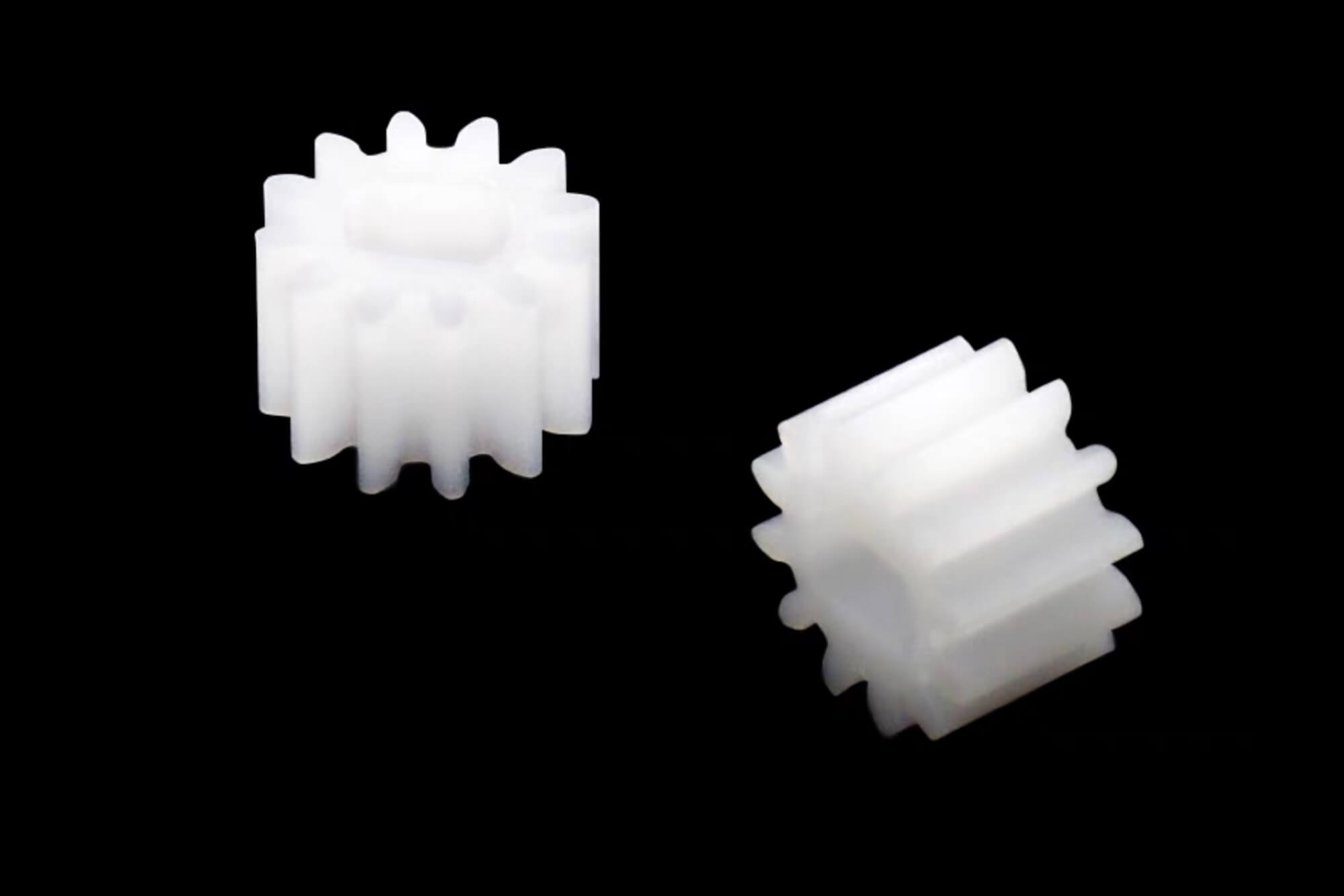
- Spur Gears: These are the simplest and most commonly machined plastic gears. They’re great for transmitting motion between parallel shafts in applications like automated packaging machines.
- Helical Gears: Slightly more complex, these are quieter and smoother than spur gears, making them ideal for printers, medical devices, and other noise-sensitive environments.
- Bevel Gears: Used where the direction of a shaft’s rotation needs to change, such as in angled tool drives or compact appliances.
- Worm Gears: These offer high gear reductions in a small package and are common in compact motorized systems where space is tight, like robotic joints or lab instruments.
- Rack and Pinion: Converts rotational motion into linear motion, frequently used in CNC machines and linear actuators.
- Internal Gears: These work with spur gears to create more compact, enclosed drives found in consumer electronics and servo drives.
Each of these gear types can be machined from plastics for very different reasons—some for noise reduction, others for corrosion resistance, and some because they need to be customized quickly. I’ve worked with all of them at some point, and the material and machining strategy always depends on the end-use environment.
You can refer to the table “Plastic Gear Types and Applications” above for a summarized view of their advantages and application areas.
III. Choosing the Right Material for Machined Plastic Gears
Selecting the right plastic material is one of the most important steps when designing and machining plastic gears. Different materials offer unique strengths—and weaknesses—when it comes to wear resistance, thermal performance, dimensional stability, and machinability.
Over the years, I’ve worked with a range of materials for custom plastic gears. Some are ideal for high-speed, high-precision gears. Others are better for shock absorption or low-cost prototyping. The key is understanding the trade-offs.
“Plastic Gear Material Comparison” table
| Material | Machinability | Wear Resistance | Heat Resistance | Friction Coefficient | Best Use Case |
|---|---|---|---|---|---|
| Delrin | Excellent | High | Moderate | Low | General-purpose gears, excellent dimensional stability |
| PA6 / PA66 (Nylon) | Good | Medium | Moderate | Medium | Low-cost applications with moderate strength needs |
| PEEK | Moderate | Very High | Very High | Very Low | High-performance gears in aerospace or medical |
| UHMW-PE | Fair | Medium | Low | Very Low | Impact-resistant parts in food processing equipment |
| PTFE | Poor | Low | High | Very Low | Low-friction, chemical-resistant precision parts |
| Polycarbonate (PC) | Good | Medium | High | Medium | Transparent gears or components under moderate load |
Below is a detailed comparison of popular plastic gear materials:
Let’s break down a few highlights:
🔹 POM (Delrin)
POM is my go-to for most machined plastic gears. It offers excellent dimensional stability, low friction, and machines beautifully. It’s suitable for most general-purpose applications where moisture, heat, or chemicals are not extreme.
🔹 PA6 / PA66 (Nylon)
Nylon is widely available and inexpensive. It’s strong and wear-resistant, but it tends to absorb moisture and swell over time. I usually reserve it for environments with controlled humidity or where strength outweighs dimensional accuracy.
🔹 PEEK
PEEK is one of the most robust materials available for plastic gear machining. It has incredible heat resistance, chemical resistance, and dimensional stability. It’s perfect for aerospace, medical, or high-speed robotics—but it’s also one of the most expensive materials you can use.
🔹 UHMW-PE
Ultra-high-molecular-weight polyethylene is extremely impact-resistant and has excellent slip properties. I use it where parts need to be highly durable and shock-absorbing, like conveyor gears or processing equipment in food and beverage lines.
🔹 PTFE (Teflon)
While PTFE isn’t known for its strength, it’s incredibly slippery and heat-resistant. I don’t recommend it for high-load gears, but it’s useful in chemical processing or lab environments where friction and reactivity are concerns.
🔹 Polycarbonate (PC)
Polycarbonate is tough and transparent. It’s not ideal for every application due to its moderate wear resistance, but it’s great when visual inspection of gear movement is required—like in educational or demonstration models.
IV. Gear Machining Methods for Plastics
Once you’ve selected the material for your plastic gears, the next critical decision is how to machine them. There’s no single best method—it depends on your design, quantity, precision requirements, and equipment availability.
In my shop, I’ve used nearly all of these methods at some point depending on project needs. Here’s how I break them down.
📌 Overview of Gear Machining Techniques
Table of gear machining methods for plastic gears:
| Method | Best for Gear Type | Pros | Cons |
|---|---|---|---|
| CNC Milling | Spur, Helical, Internal | High accuracy, flexible profiles, easy setup | May require multiple setups |
| CNC Turning | Round blanks, Worm gears | Great for shafts and concentric features | Limited to simple gear shapes |
| Gear Hobbing | Spur, Helical (high precision) | Efficient for gear teeth, scalable to small batches | Requires special hobbing tools |
| Gear Shaping | Internal, External, Close pitch gears | Good for tight spaces and internal profiles | Slower than hobbing, limited by tool access |
| 3D Printing + Machining | Prototype gears, custom profiles | Fast iteration, low setup cost | Lower mechanical performance unless post-processed |
| Injection Molding | High-volume production gears | Lowest cost per part at high volume | High tooling cost, long lead times |
Refer to the “Plastic Gear Machining Methods Comparison” table above for a side-by-side breakdown.
Let’s explore the most common methods:
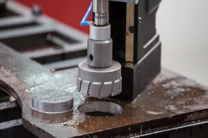
🔹 CNC Milling
CNC milling is one of the most flexible and widely used methods for plastic gear fabrication. You can create spur gears, helical gears, and even internal gears using custom CAM toolpaths. Milling allows excellent control over tooth profiles, spacing, and root geometry.
I typically use 3- or 4-axis milling to generate gear blanks and tooth profiles for small-batch custom gears.
When to use it: Small runs, high precision, customizable geometries
Watch out for: Tool deflection in soft plastics and burrs on fine teeth
🔹 CNC Turning
If you’re machining a worm gear or preparing a round blank, CNC turning is your friend. It’s ideal for concentric operations—shaft machining, flange integration, or preforming gear stock before hobbing.
When to use it: Round features, hollow gears, concentric gear bases
Watch out for: Overheating during long cuts—use sharp tools and proper coolant
🔹 Gear Hobbing
When I need excellent tooth accuracy and repeatability, I go with hobbing. It’s fast, scalable, and produces clean, consistent teeth. However, it requires a hobbing machine or hobbing head attachment, and dedicated tools for each gear pitch.
When to use it: Moderate-to-high quantity, standard gear types
Watch out for: Tool setup time and cost if you’re making many gear sizes
🔹 Gear Shaping
Shaping is great for gears that are hard to hob—like internal gears or those with tight tooth spacing. It’s slower than hobbing, but more versatile in terms of gear type and layout.
When to use it: Internal gears, tight gearboxes, precision fitments
Watch out for: Limited by tool stroke and machine access to complex geometries
🔹 3D Printing + Machining (Hybrid Method)
Sometimes I combine additive and subtractive methods. I’ll 3D print a gear blank or rough gear body, then finish the teeth using CNC milling or shaping. This works well for prototyping or concept testing.
When to use it: Fast iteration, unique gear shapes
Watch out for: Surface quality and mechanical strength—post-processing helps
🔹 Injection Molding (for Comparison)
Even though we’re focused on machining, I always compare to injection molding. It’s unbeatable for high-volume production, but it demands expensive molds and long lead times.
When to use it: Large batch production where per-part cost matters
Watch out for: High initial cost and mold modification difficulty
🧠 My Recommendation?
If you’re creating 5–50 gears and need tight tolerances, CNC milling or hobbing are the best. If you’re dealing with internal geometries, gear shaping is hard to beat. For prototypes or unique geometries, 3D printing + machiningworks wonders.
Each method has its place—and understanding when to use what will save you time, money, and rework.
V. Machining Parameters and Tooling for Plastics
When it comes to machining plastic gears, the right parameters can make or break your results. Use the wrong speed or feed rate, and you’ll melt the plastic, create burrs, or even warp the entire gear. I’ve experienced all of these problems at some point in my early work. Fortunately, optimizing your process comes down to understanding how each plastic responds to heat and force.
This is table of “Machining Parameters for Plastic Gear Materials“
| Material | Recommended Spindle Speed (RPM) | Feed Rate (mm/min) | Coolant Use | Tool Type |
|---|---|---|---|---|
| POM (Delrin) | 10,000 – 15,000 | 800 – 1500 | Optional (air preferred) | Carbide, uncoated |
| Nylon (PA6/PA66) | 8,000 – 12,000 | 700 – 1200 | Required (mist or air) | Carbide, sharp edge |
| PEEK | 6,000 – 10,000 | 500 – 900 | Required (oil or air) | Coated carbide |
| UHMW-PE | 6,000 – 8,000 | 400 – 800 | Required (air only) | Polished carbide |
| PTFE | 5,000 – 7,000 | 300 – 600 | No coolant (dry cut) | PTFE-specialized |
| Polycarbonate (PC) | 8,000 – 10,000 | 600 – 1000 | Optional (air/mist) | Carbide, sharp end |
I’ve compiled a reference table (see “Machining Parameters for Plastic Gear Materials” above) that reflects the most reliable settings I’ve used in real projects.
Let’s walk through what matters most when cutting plastic gears.
🔹 Spindle Speed and Feed Rate
Plastic materials tend to soften or deform at relatively low temperatures compared to metals. That means you need to maintain a high enough cutting speed to get a clean chip, but not so high that friction overheats the part.
For example:
- POM (Delrin) can be machined quickly at 10,000–15,000 RPM with a moderate feed rate. It’s dimensionally stable and forgiving.
- PEEK, being tougher and more abrasive, requires slower spindle speeds—6,000–10,000 RPM—and benefits from coated carbide tools to extend tool life.
When working with PTFE or UHMW, I’ve learned to avoid coolants altogether and use air blasts or dry cutting. These materials smear if overheated, so keeping the toolpath shallow and tools sharp is critical.
🔹 Tool Selection
I always use sharp carbide tools for plastic gear machining. Dull tools generate heat and cause plastic to soften, melt, or stick to the cutter. For materials like UHMW and PTFE, polished cutters help reduce friction and chip adhesion.
If you’re machining intricate gear profiles or small diameters, I recommend single-flute end mills. They reduce cutting heat and provide more room for chip evacuation.
For production environments, diamond-coated or polished carbide tools give the best surface finish and reduce burrs.
🔹 Coolant or Not?
Coolant use depends on material type:
- POM and PC handle mist cooling or even dry machining well.
- PEEK and Nylon perform better with directed air or oil-based coolant.
- PTFE? Dry cut only. Any coolant will mess with the part finish and tool performance.
In most cases, I prefer air blast or minimum quantity lubrication (MQL) over flood coolant, since it avoids material swelling or absorption issues.
⚙️ Fixturing and Workholding
Plastic parts can flex, warp, or even chatter under load, especially during gear tooth machining. Always:
- Use flat, well-supported fixtures
- Avoid over-tight clamping (it can deform the part)
- Consider vacuum tables for thin components or delicate gear blanks
I sometimes use custom soft jaws or sacrificial fixturing plates when running nylon gears, since they’re prone to slight deformation if over-clamped.
🔧 Final Tips from the Shop Floor
- Avoid re-cutting chips—they heat up quickly and mar the surface
- Always de-burr gently; aggressive deburring can damage gear teeth
- Inspect early and often—plastics change dimensionally with temperature
VI. Tolerances and Surface Finish in Plastic Gear Machining
In precision applications, even small errors in a gear’s dimensions can lead to noise, wear, or total failure. That’s why understanding tolerances and surface finish is critical when machining plastic gears.
From my own experience, machining plastics demands a different mindset than working with metals. Materials like nylon or UHMW-PE are more elastic and prone to thermal expansion. If you hold them to tight metal-like tolerances, you’ll run into problems once the gear is under load or temperature changes.
📏 Standard Gear Tolerances (AGMA/DIN Overview)
In practice, I typically aim for AGMA Q8–Q10 or DIN 7–9 class tolerances on machined plastic gears. These classes allow for:
- Tooth profile deviation: ±0.01 to ±0.03 mm
- Center distance variation: ±0.02 mm
- Runout: ≤0.03 mm for most applications
Of course, tolerances vary by gear type, module, and material. But here’s a practical rule of thumb:
“The softer the plastic, the looser the tolerance should be—unless you can control the operating environment very tightly.”
🧪 Surface Finish and Its Impact
Surface finish matters—especially for gear noise and wear. Smooth tooth surfaces reduce friction, minimize vibration, and improve lifespan. But getting a perfect finish on plastic isn’t always easy.
Machined Finish Goals:
- Functional gears (automation, robotics): Ra 1.2–1.6 µm
- Noise-sensitive gears (printers, medical): Ra 0.8–1.0 µm
- Optical or precision fit gears: Ra ≤ 0.6 µm (post-processed)
How I Improve Surface Finish:
- Use sharp, polished tools — especially for final passes
- Take light finishing cuts (0.1–0.2 mm step-down)
- Use fine-grain polishing tools for burr removal
- Maintain stable temperatures during machining
- Inspect frequently to avoid tool wear degradation
📌 Real-World Example
On a recent project, we machined a set of POM spur gears for a medical automation client. Initially, they asked for AGMA Q11 tolerance—but after testing under fluctuating lab temperatures, we adjusted to Q9 and polished the teeth. Result? Quieter operation and zero gear binding after 1,000 cycles.
💬 Final Word on Tolerances
Plastic gear tolerances aren’t about chasing the smallest number—they’re about function, environment, and repeatability. Know the load, know the heat, and design your tolerances accordingly.
VII. Common Problems in Plastic Gear Machining and How to Solve Them
No matter how carefully you set up your machine, machining plastic gears introduces a unique set of challenges that you rarely see when working with metals. I’ve had my share of failed cuts, warped parts, and deformed teeth. The good news is that most of these issues are predictable—and solvable—once you know what to watch for.
Below, I’ve broken down the most common problems I’ve encountered when machining plastic gears and how to address each one with practical, experience-based solutions.
⚠️ 1. Burr Formation on Gear Teeth
The problem:
Most plastics, especially soft ones like nylon or UHMW, tend to form burrs at the edges of gear teeth. These burrs interfere with mesh quality, increase noise, and wear down quickly during operation.
How to solve it:
- Use sharp, polished cutting tools—dull tools “smear” instead of cut.
- Optimize feed and speed—too fast = melting, too slow = tearing.
- Deburr manually with a soft brush, scalpel, or ultrasonic bath.
- Avoid aggressive chamfers; instead, apply a light edge break (0.1–0.2 mm).
⚠️ 2. Heat Deformation During Machining
The problem:
Plastics are more heat-sensitive than metals. Even moderate cutting temperatures can lead to localized melting or distortion, especially in small-toothed gears.
How to solve it:
- Lower spindle speeds and take light passes.
- Use air blast cooling instead of flood coolant.
- Consider step machining: rough pass > cool down > finish pass.
- Store plastic stock in a climate-stable room to reduce expansion variability.
⚠️ 3. Dimensional Inconsistencies
The problem:
Plastics can expand from both heat and moisture absorption, leading to tolerance drift—even after machining. You may cut a perfect gear and find it out-of-spec after 24 hours.
How to solve it:
- Account for thermal expansion in your tolerances.
- Dry hygroscopic materials (like nylon) before machining.
- Let parts rest for 12–24 hours before final inspection or assembly.
- Use stress-relieving annealing on materials like PEEK or Delrin if tolerances are critical.
⚠️ 4. Poor Surface Finish
The problem:
Surface roughness affects not only gear efficiency but also lifespan and noise. A poorly finished tooth face can cause chattering or early failure under load.
How to solve it:
- Use single-flute tools for finishing passes.
- Reduce feed rate and step-over for final cuts.
- Inspect tool wear regularly; change cutters more often than with metals.
- Polish gear teeth using micro-abrasive pads or vapor polishing (for PC/ABS).
⚠️ 5. Tool Clogging and Chip Welding
The problem:
Some plastics—especially sticky ones like PTFE or PVC—tend to melt, wrap around the tool, or clog flutes, leading to poor finish or tool breakage.
How to solve it:
- Use compressed air or minimum quantity lubrication (MQL).
- Choose tools with wide flutes and sharp rake angles.
- Avoid climb milling if chip welding is observed; use conventional milling.
- Use anti-stick tool coatings (TiN, TiAlN, or diamond-like carbon).
⚠️ 6. Tool Deflection in Small Parts
The problem:
Plastic gear teeth are often tiny and fragile. Cutting them with long, small-diameter tools leads to deflection and profile inaccuracy.
How to solve it:
- Shorten tool overhang as much as possible.
- Use carbide tools with smaller helix angles to reduce lateral force.
- Break up operations into multiple shallow passes.
- Use gear-specific CAM strategies with constant engagement paths.
📌 Real-World Lesson
While machining a batch of 20 nylon helical gears for a customer in the automation industry, I noticed inconsistent engagement across batches. It turned out the ambient humidity varied week to week, and the nylon absorbed enough moisture to change size mid-process.
We solved it by pre-drying the stock, implementing temperature/humidity control in the shop, and switching from nylon to POM for dimensional stability. That project taught me that with plastics, environmental factors matter as much as tooling.
✅ Final Thought
Plastic gear machining is a balancing act between heat, force, material behavior, and environment. The more you work with it, the more you learn to predict and preempt problems before they cost you time or quality.
VIII. Case Study: CNC Machining of a Nylon Helical Gear
When people ask me about machining plastic gears, I often point them to a project I did for a mid-sized robotics company that needed a small batch of nylon helical gears. This wasn’t just a typical gear—they needed a specific tooth profile, tight center distance tolerance, and reduced gear noise for a lightweight robotic arm joint.
Let me walk you through how we handled it from design to delivery.
🔧 Project Overview
- Material: PA66 (Nylon 66)
- Gear Type: Helical, 20 teeth, module 1.5, 25° helix angle
- Quantity: 30 pieces
- Application: Lightweight actuator in robotic joint
- Key Requirements:
- Low noise under moderate load
- Consistent tooth profile
- Minimal post-processing
🛠️ Design and CAM Setup
We received a STEP file from the client, but I always run a secondary verification in Fusion 360 or SolidWorks to confirm:
- Module and pressure angle
- Addendum, dedendum accuracy
- Proper root fillet radius to avoid stress concentration
After confirming gear geometry, we set up CAM operations as follows:
- Face and Rough Blank:
Turned down the outer profile and bore using CNC lathe - Tooth Profile Milling:
Used 4-axis CNC with custom helical toolpath- Tool: Single-flute carbide cutter, 2 mm diameter
- Spindle: 9,000 RPM
- Feed rate: 600 mm/min
- Coolant: Dry cut + air blast
- Finishing Passes:
Light spring pass with reduced step-over (0.05 mm) to improve surface finish - Deburring:
Manual rotary brush deburring followed by light ultrasonic cleaning
📐 Tolerance Goals & Achievements
| Feature | Target Tolerance | Final Measured Range |
|---|---|---|
| Tooth Pitch Error | ±0.02 mm | ±0.015 mm |
| Runout on Bore to Teeth | ±0.03 mm | ±0.02 mm |
| Face Width Flatness | ±0.05 mm | ±0.03 mm |
| Surface Finish (Ra) | ≤1.2 µm | ~0.9 µm average |
These numbers exceeded expectations, especially considering nylon’s tendency to absorb moisture and move during machining.
🧪 Post-Machining Handling
After machining, we:
- Dried parts for 6 hours at 50°C to minimize internal stress from moisture gain
- Packaged gears in vacuum-sealed bags with desiccants for shipping
- Included runout and tooth accuracy reports with each shipment
The client later told us they installed all 30 units with zero adjustments needed—a rare and satisfying outcome in custom gear jobs.
🧠 Lessons Learned
- Nylon must be dried both before and after machining to maintain dimensional stability.
- For helical gears, any slight pitch angle deviation becomes noticeable in multi-axis systems.
- Air cooling works better than mist on nylon—it avoids surface contamination and part swelling.
✨ Why This Case Matters
This job wasn’t about volume or profit—it was about precision and trust. For teams developing mechatronics and robotics, getting gears right on the first try saves weeks of debugging. And when you’re machining plastic gears, that precision is more art than brute force.
IX. Comparing Machined vs Molded Plastic Gears
If you’ve ever had to decide between machining plastic gears and molding them, you know it’s not always a straightforward call. I’ve worked with startups trying to prototype fast and OEMs ordering tens of thousands of gears, and they care about very different things.
Let’s break down the key differences—when to machine, when to mold, and why choosing the right method at the right time saves money, time, and headaches.
🆚 Machined Plastic Gears
| Attribute | Description |
|---|---|
| Setup Cost | Low (no tooling needed) |
| Lead Time | Short (1–7 days typical) |
| Batch Size | Ideal for 1–500 parts |
| Customization | Very high; change gear profile without added cost |
| Precision | High (AGMA Q8–Q11 achievable) |
| Tooling Investment | None |
| Unit Cost (Low Qty) | Moderate to high |
| Speed of Iteration | Very fast |
🛠️ Best for: prototyping, low volume, R&D, and custom applications
🏭 Molded Plastic Gears
| Attribute | Description |
|---|---|
| Setup Cost | High (mold tooling required) |
| Lead Time | Long (3–6 weeks including tooling) |
| Batch Size | Economical for 5,000+ pieces |
| Customization | Low; design locked once mold is made |
| Precision | Moderate to high depending on mold quality |
| Tooling Investment | High ($1,000–$10,000+ depending on complexity) |
| Unit Cost (High Qty) | Very low (as little as $0.10/gear) |
| Speed of Iteration | Slow, especially if design changes are needed |
🏭 Best for: mass production, long-term stable designs, consumer products
📌 When I Recommend Machining
- You need 10 to 1000 custom gears for prototyping or testing.
- You’re working on functional prototypes where gear behavior matters.
- The gear needs tight tolerances or exotic materials (like PEEK or carbon-filled nylon).
- The project is in early development, and the design may still change.
Machining is your friend when speed, flexibility, or complexity outweigh part cost.
📌 When Molding Makes More Sense
- You’ve locked the gear design and need thousands or millions of units.
- The application tolerates minor dimensional variation.
- You have consistent material availability and a stable supply chain.
- You’re optimizing for cost per part, not tooling agility.
Molding is unbeatable on volume, but painful if you’re still experimenting.
🎯 Hybrid Approach? Yes.
On several projects, we used a hybrid strategy: start with CNC-machined gears to test meshing and durability, then move to molding once the design is finalized.
We even machined aluminum or POM test molds in-house for ultra-short production runs (100–200 units), which served as a bridge between the prototyping and production stages.
⚖️ Quick Comparison Summary
| Factor | Machining | Molding |
|---|---|---|
| Cost Per Unit | High (small qty) | Low (large qty) |
| Initial Cost | Low | High |
| Flexibility | Very High | Very Low |
| Tooling Needed | No | Yes |
| Lead Time | Short (1–7 days) | Long (3–6 weeks) |
| Ideal Volume | 1–500 parts | 5,000+ parts |
| Design Change | Easy | Expensive/time-consuming |
One of my clients had a medical device prototype that used five different plastic gear profiles. We machined them all within four days. If they had gone the molding route, they’d have spent $15,000+ and waited over a month—only to discover they needed to revise two of the gears.
Machining saved them not only money, but their entire product launch timeline.
X. Future Trends: Hybrid Manufacturing and Custom Gear Solutions
The way we design, prototype, and produce plastic gears is evolving—fast. Thanks to advancements in CNC automation, 3D printing, and digital design workflows, we’re entering a new age of on-demand gear manufacturing.
In the past, if you wanted a gear, you either machined it by hand or paid big money for tooling. Today, small teams and even solo inventors can create highly functional, production-grade gears within days using hybrid technologies.
Here’s where the industry is heading:
🧩 1. CAD-to-GearCAM Automation
Modern CAM tools now support direct import of gear geometries from popular CAD platforms. This makes it possible to:
- Auto-generate toolpaths from standard gear models (involute, custom, worm)
- Apply pre-tested strategies for materials like POM and nylon
- Adjust tooth clearance and backlash digitally before cutting
I’ve personally seen workflow time drop from 4 hours to 30 minutes using integrated gear modules.
🖨️ 2. 3D Printing + Machining Integration
Hybrid manufacturing is booming. The idea is to 3D print the blank or core geometry, then machine only the critical faces and teeth for precision.
Use cases I’ve worked on include:
- 3D printed ABS gear bodies with CNC-machined teeth
- SLA-printed masters for silicone molds, then casting wear-resistant polyurethane gears
- Multi-material prints with embedded metal hubs + plastic teeth
It’s faster, cheaper, and allows for ultra-rapid iteration.
🔄 3. Mass Customization of Gearboxes
Gear suppliers are now building platforms where you can:
- Configure your own gear online (module, teeth, pitch, material)
- Receive machined gears in 48–72 hours
- Download CAD and spec sheets instantly
This is ideal for engineers building one-offs, robotic kits, or machine prototypes. Companies like SDP/SI, igus®, and Misumi are investing heavily in this direction.
🌍 4. Sustainable Materials and Circular Prototyping
With increasing attention on sustainability, recyclable plastics (like rPET or bioplastics) are entering the gearmaking space. I’ve tested PLA gears for short-life prototypes and they’re holding up surprisingly well in low-load cases.
Some labs are even exploring closed-loop prototyping systems, where failed gears are shredded, re-pelletized, and re-printed for test iteration.
🧠 Final Thought
The future of plastic gear machining is:
- Flexible
- Digital
- Personalized
- Affordable at any scale
As someone who’s built gears for everything from drones to lab robots, I can say with confidence: You don’t need to be a manufacturer to make great gears anymore.
FAQ
- What plastic materials are best for machining gears?
→ POM (Delrin), Nylon, PEEK, and UHMW-PE are popular choices for different load and temperature needs. - Can I make plastic gears using a 3-axis CNC mill?
→ Yes, with custom toolpaths or specialized gear milling CAM software. - Is gear hobbing suitable for plastic gears?
→ Absolutely, especially for spur and helical gears in medium batches. - What tolerances can I achieve with plastic gear machining?
→ AGMA Q8–Q11 or ±0.02 mm is realistic with good setup and tooling. - Should I use coolant when machining plastic gears?
→ Prefer air blast or dry cutting; many plastics absorb or react poorly to fluids. - Are machined plastic gears suitable for production?
→ For low-to-medium volumes or custom specs, yes. Beyond 1,000 units, molding may be better. - Can I machine internal plastic gears?
→ Yes, using shaping, broaching, or multi-axis CNC. - Is 3D printing a viable way to produce gears?
→ For prototypes or non-load-bearing parts, yes. For precision or durability, machine the teeth. - How do I deburr small plastic gears?
→ Soft brushes, micro-polishing pads, or ultrasonic cleaners work well. - What causes plastic gears to deform during machining?
→ Heat buildup and internal stress. Use sharp tools and light passes. - Can I machine gear teeth on both sides of a gear blank?
→ Yes, with proper fixturing and indexing—often done in 2 setups. - Are machined plastic gears noisy?
→ No—they’re generally quieter than metal gears, especially when well-finished. - Can I machine gears from transparent plastic?
→ Yes—PC (polycarbonate) and Clear PETG are commonly used for demo or visual assemblies. - What is the minimum batch size for machining to be economical?
→ Often 1–50 parts; great for prototyping or testing. - Can I design my own plastic gear in CAD?
→ Yes—Fusion 360, SolidWorks, KISSsoft, and Gearotic offer powerful tools. - Do I need post-processing after machining?
→ Usually yes—deburring and stress relief improve long-term performance. - Can I machine gears that will later be overmolded or inserted?
→ Definitely—just maintain tolerance and proper surface prep on bonding surfaces.
Further Reading & Authoritative References
- AGMA Gear Quality Standards (Q3–Q15) The American Gear Manufacturers Association (AGMA) provides detailed classifications for gear tolerances, including those applicable to plastic gears. Their standards, such as AGMA 2000-A88, offer insights into gear quality numbers and inspection methods. 👉 AGMA Gear Classification and Inspection Handbook
- Engineering Plastics Overview – Wikipedia This comprehensive article outlines various engineering plastics, including POM, Nylon, and PEEK, discussing their properties and applications in mechanical parts like gears. 👉 Engineering Plastics
- Guide to Machining Plastic Parts – Mitsubishi Chemical Group Mitsubishi Chemical Group offers a practical guide for machinists, detailing best practices for machining engineering plastics, including recommendations on tooling, coolants, and machining parameters. 👉 Machinist’s Toolkit
- Hobbing for Plastic Gears – Helios Gear Products This resource discusses the suitability of hobbing processes for plastic gears, highlighting considerations for tool selection and machining parameters specific to plastics. 👉 Hobbing for Plastic Gears
- Thermoplastics – Wikipedia An in-depth look at thermoplastic materials, including their characteristics, processing methods, and common applications in manufacturing components like gears. 👉 Thermoplastic
- 3D Printing Gears – Instructables A practical guide exploring the use of FDM 3D printing for creating plastic gears, discussing material choices, design considerations, and post-processing techniques. 👉 A Practical Guide to FDM 3D Printing Gears
These resources provide valuable insights and detailed information to complement the topics discussed in this article.Feel free to explore them to deepen your understanding of plastic gear machining and related subjects.
Other Articles You Might Enjoy
- Everything About Types of Gears: Straight, Helical, Bevel, and More
Introduction When I first started learning about types of gears, I thought they all looked alike: just round devices with teeth that mesh together. But as I dug deeper, I…
- How to Choose Cost-Effective Rack and Pinion Gear? — A Must-Read for Procurement Engineers
Introduction: Why Procurement of Rack and Pinion Gear Matters I still remember the first time I was asked to source rack and pinion gear for a CNC system. Back then,…
- Steering Gear Box CNC Production: Cost, Process, and Quality Guide
Part 1: Introduction If you’re like me and work with automotive, heavy machinery, or any industry that involves precision mechanical systems, you’ve probably encountered the term steering gear box many times. A steering…
- Pinion Gear and CNC Machining: A Comprehensive Guide
Introduction If you're involved in manufacturing or mechanical design like me, you've likely come across the term pinion gear frequently. A pinion gear is simply the smaller gear that meshes…
- Unlock Gear Ratio Chart Power For Machinist: Machining Made Simple
Introduction: Unleashing the Power of Gear Ratio Charts for Machinists Gear ratio charts are more than just a bunch of numbers on a page—they’re a machinist’s secret weapon. I’ve spent…
- Custom Worm Gears Manufacturing with CNC Machining Expertise
Introduction to Worm Gears and CNC Worm gears are a fascinating and essential component of many modern machines. They might look simple at first glance—a helical gear engaging with a…
- Master CNC Machining for Planetary Gear: Design, Tools, and Applications
What Is a Planetary Gear and Why Is It Important? When discussing advanced mechanical systems, few designs are as efficient and versatile as the planetary gear. Known for its compact structure…
- How to Procure and Machine Custom Helical Gear: A Step-by-Step Guide for Manufacturers
Introduction Custom helical gear is integral components in machinery where precision, performance, and durability are non-negotiable. From personal experience, I’ve found that whether you're designing a state-of-the-art automotive transmission, an…
- Straight Cut Gears Explained: What They Are and Why They Matter in CNC Machining
Introduction If you’ve worked with high-performance machinery or explored CNC machining, you’ve likely come across the term straight cut gears. These gears are renowned for their efficiency in transferring power…
- Spur Gear Machining: A Complete Guide to Design and Manufacturing
Introduction: The Role of Spur Gears in Modern Industry I’ve worked with mechanical systems for several years, and along the way, I’ve realized how crucial a spur gear can be.…