Grooving on CNC lathes is a multi-step operation crucial for creating specific, high-quality parts. Grooving usually involves cutting narrow slots of a particular depth on cylindrical, conical, or end faces of parts. The shape of the groove (at least the important part of it) depends on the shape of the cutting tool. Grooving tools are used for various special machining operations. Similar to other tools, grooving tools are typically carbide inserts mounted on special tool holders. The variety of grooving inserts is extensive, ranging from single-edge to multi-edge inserts, produced in nominal sizes. Using multi-edge grooving inserts can reduce production costs and increase productivity.
Grooving Basics
Grooving tools can be used for both external and internal profiles on different workpieces using various inserts. The main difference between grooving and turning is the direction of the cut. Turning tools can cut in multiple directions, whereas grooving tools generally cut in a single direction. One exception is often called a relief groove, usually cut at a 45° angle, requiring the insert’s angle to match the feed angle (typically 45°). Chamfering in grooving is another application of two-axis linkage, technically part of the turning operation. Although grooving inserts are not designed for turning, they can be used for minor turning tasks, such as cutting small chamfers. When chamfering in grooves, the cutting depth is always small, and the feed rate is low.
Major Applications of Grooving
Grooving is a significant part of CNC lathe machining, with numerous applications across various industries. Some primary purposes of grooves include ensuring parts fit face-to-face or shoulder-to-shoulder and creating lubrication grooves to allow smooth flow of lubricants between connected parts. There are also pulley or V-shaped grooves for belt drives, O-ring grooves for seals, and many other specific grooves. While some grooves are unique to specific industries, most use standard groove shapes.
Grooving Standards
For CNC programmers, grooving is often not particularly challenging, and some groove programming can be simpler than other operations. However, there are also very complex grooves in various industries that present significant challenges in programming and machining. Regardless of the complexity, thorough analysis of groove specifications and careful planning are necessary before programming. When planning a groove machining program, consider the following three essential standards:
- Groove shape
- Groove location on the workpiece
- Groove size and tolerance
Many grooves may not meet the highest quality standards because they don’t require high precision. However, high-precision grooves require the programmer to know the correct handling methods, ensuring surface quality and tolerance are maintained.
Groove Shapes
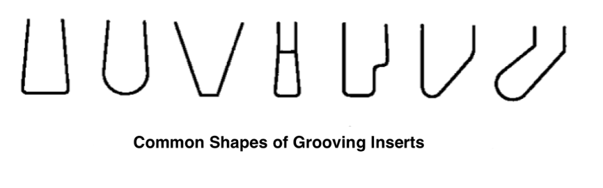
Estimating the groove shape is the first step before programming. The groove shape is determined by the part drawing and its purpose. When selecting a grooving tool, the groove shape is the most crucial factor. Grooves parallel to the machine’s spindle and with sharp corners require square inserts. Grooves with radii need inserts with matching or slightly smaller radii. Special grooves, like angled ones, require inserts with angles matching the groove’s angle on the drawing. Formed grooves need inserts with the same shape. Figure 1 shows common grooving insert shapes.
Figure 1:
Nominal Size of Inserts
In many grooving operations, the groove width exceeds the maximum nominal width of the insert. Nominal sizes are available in various tool catalogs, with common widths being 1mm, 2mm, 3mm, or 1/32in, 3/64in, 1/16in, 1/8in, etc. For example, a groove width of 0.276in can be machined using an insert with a nominal width closest to it, like 0.250in. This involves at least two cuts, one or more rough cuts, and at least one finish cut. For higher tolerance requirements or faster tool wear, another tool may be used for finishing (as shown in Figure 2).
Figure 2:
Modifying Inserts
Sometimes, programmers may need to modify standard inserts to match groove dimensions or shapes. There are two main methods: custom-made inserts for specific grooves and adjusting existing tools’ dimensions internally. Generally, using non-customized tools and inserts is preferable. However, in special cases, modifying standard tools or inserts to fit specific tasks may be necessary. For grooving, modifications might include extending the insert’s cutting depth or changing the tool radius. Avoid altering the groove shape unless absolutely necessary, as this can delay production and increase costs.
Groove Location
The groove’s location on the workpiece is specified by the part drawing, falling into one of three categories:
- Grooving on cylinders (diameter cutting)
- Grooving on cones (tapered cutting)
- Grooving on end faces (shoulder cutting)
While grooves aren’t limited to these types, practical considerations often restrict focus to these three locations. These can be external or internal grooves.
Groove Dimensions
Groove dimensions are crucial for selecting the appropriate insert. Dimensions include width, depth, and corner details. A groove cannot be machined with an insert wider than the groove. Similarly, an insert or tool holder longer than the groove depth can’t be used. However, narrower inserts can be used for multiple cuts to machine a wider groove, and longer tools can machine shallower grooves. Groove dimensions determine the machining method. If the groove width equals the insert width, a single cut is needed. The tool moves in to cut and retracts quickly. For correct programming, know the groove width, depth, and its position relative to a known reference point on the workpiece.
Simple Grooving Programming
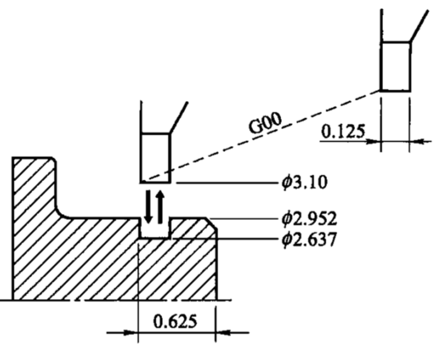
The simplest grooves have the same depth and shape as the cutting edge of the tool, as shown in Figure 3. Programming such grooves is straightforward: move the tool rapidly to the starting position, feed to the groove depth, and retract rapidly to the starting position, completing the groove. This method requires no chamfering, surface quality control, or special techniques. It may lack the best quality but is practical and doesn’t require precision machining. This basic groove programming is an excellent starting point for learning more advanced techniques.
Figure 3:
Precise Grooving Techniques
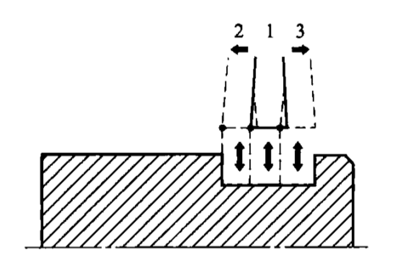
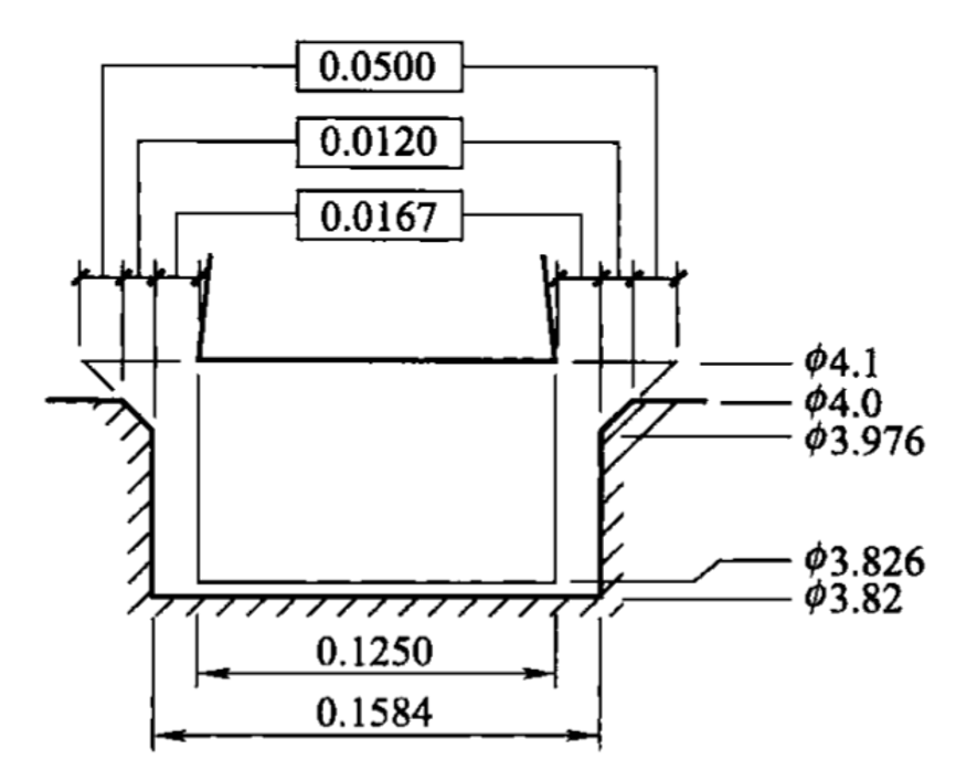
Achieving precise grooves requires additional effort but results in high-quality grooves. The best method is roughing and finishing each side, leaving a 0.006 margin at the groove bottom, and chamfering the sharp corners at 0.012, as shown in Figure 4.
Figure 4:
electing Groove Width
In program 03602, a standard 0.125in grooving insert is used for a 0.1584in wide groove. Choosing the closest standard width insert, like 5/32in (0.15625in), is not ideal due to the small margin left on each side. A narrower 1/8in (0.125in) insert is better, providing more significant margin for multiple cuts. Once the tool and initial values are set, including the offset number (03), spindle speed (400ft/min), and speed range (M42), the programming can begin.
Machining Method
With the tool selected and turret position determined, the actual machining method can be planned. The simple in-out method is insufficient for high-quality grooves. Multiple cuts are necessary, calculated using the formula:

Where ( C_{min} ) is the minimum number of cuts, ( G_w ) is the groove width, and ( T_w ) is the insert width.
Achieving Quality
Quality grooves require planning and experience, ensuring equal machining allowance on both sides, leading to better cutting conditions, surface quality, and tool life. This method involves three cuts, roughing the middle and finishing each side. This allows control over groove position and width, with careful programming to meet tolerance requirements.
Surface Quality
Ensuring high-quality surface finish involves using appropriate speeds, feeds, and coolants, along with the correct tool conditions and the suggested even distribution of cuts. High-quality grooves demand precision in position, size, and finish, ensuring functional and aesthetic standards.