Insert Shapes and Naming Standards
International Insert Naming Standards
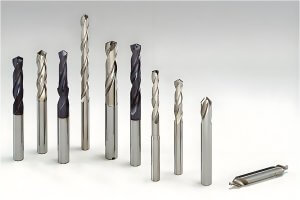
The naming of CNC turning inserts follows international standards, which mainly include the shape, material, and suitable machining conditions of the inserts. The shape of the inserts is represented by letters, for example:
- C stands for an 80-degree diamond insert
- D stands for a 55-degree diamond insert
- V stands for a 35-degree diamond insert
- S stands for a square insert
These shapes correspond to different machining conditions and workpiece material selections. Choosing the right insert shape is crucial for improving machining efficiency and workpiece quality.
Insert Shapes and Machining Conditions
The shape of the insert directly affects its applicable machining conditions. Here are some common insert shapes and their suitable machining conditions:
- 80-degree diamond insert (C): Suitable for roughing and semi-finishing.
- 55-degree diamond insert (D): Suitable for semi-finishing and finishing.
- 35-degree diamond insert (V): Suitable for finishing.
- Square insert (S): Suitable for roughing and semi-finishing.
The selection of inserts not only considers the shape but also combines the workpiece material and machining conditions.
Threading Inserts Naming Standards
Threading Insert Naming Rules
The naming rules for threading inserts are more complex and usually consist of multiple parts, such as 16ER12UN, where:
- 16 indicates the IC size of the insert.
- E indicates external threading.
- R indicates a right-hand insert.
- 12 indicates the pitch.
- UN indicates the thread shape is Unified National thread.
Thread Machining Methods
Thread machining methods mainly include radial infeed, flank infeed, and alternating infeed. Each method has its advantages and disadvantages, suitable for different machining scenarios. For example, radial infeed is suitable for high-efficiency machining of small-pitch threads, while flank infeed is suitable for machining large-pitch threads.
Parting and Grooving Inserts
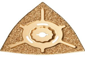
Technical Requirements for Parting and Grooving
Parting and grooving inserts need to meet specific technical requirements to ensure the stability and precision of the machining process. Selecting the appropriate insert material and groove type is crucial for improving machining efficiency.
International Standards for Toolholders
External Toolholder Naming
The naming of external toolholders usually includes the shape, size, and purpose of the toolholder, for example, SDJCR1212H07, where:
- S indicates a square toolholder.
- D indicates the type of toolholder.
- J indicates the clamping method.
- C indicates the type of insert.
- R indicates a right-hand toolholder.
- 1212 indicates the cross-sectional size of the toolholder.
- H07 indicates the overhang of the insert.
Toolholder Selection Table
Choosing the appropriate toolholder requires considering factors such as lathe specifications, distance from the tool post to the center, and internal toolholder diameter. Here is a simple selection table:
| Lathe Specifications (mm) | Distance to Center (mm) | Internal Toolholder Diameter (mm) |
|---|---|---|
| 160 | 20 | 8 |
| 200 | 25 | 12 |
| 250 | 25 | 14 |
| 300 | 32 | 20 |
| 400 | 32 | 32 |
Tool Materials and Coatings
Tool Materials
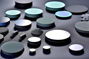
Common tool materials include high-speed steel (HSS), carbide, and ceramics. Each material has its advantages and disadvantages, suitable for different machining conditions. HSS tools are suitable for low-speed cutting, while carbide tools are suitable for high-speed cutting and mass production.
Coating Technology
The application of coating technology can significantly improve the wear resistance and service life of the tools. Common coating materials include Titanium Nitride (TiN), Titanium Carbonitride (TiCN), and Aluminum Oxide (Al2O3). Different coating materials are suitable for different workpiece materials and machining conditions.
Angles and Functions of Tool Parts
Tool Angles
The design of tool angles directly affects its cutting performance and workpiece quality. Common tool angles include rake angle, relief angle, and cutting edge angle. The rake angle determines the direction of chip flow during cutting, while the relief angle affects the tool’s durability and cutting force.
Cutting Elements
Cutting Calculation Methods
The three elements of cutting include cutting speed, feed rate, and cutting depth. These parameters directly affect machining efficiency and workpiece quality. Selecting reasonable cutting parameters can significantly improve machining efficiency and workpiece quality.
Turning Problems and Solutions
Turning Tool Problems
In turning machining, common problems include tool wear, cutting vibration, and poor chip removal. Corresponding countermeasures can be taken for these problems, such as selecting appropriate tool materials and cutting parameters, improving cooling and lubrication conditions, etc.
Other Articles You Might Enjoy
- Ceramics in CNC Machining: A Viable Alternative to Traditional Metals?
CNC Machining and Its Importance in Manufacturing Computer Numerical Control (CNC) machining stands as a critical pillar within the sphere of manufacturing, lauded for its accurate and fast production capabilities.…
- CNC Turning: A Deep Dive into Rivet Production(cnc laser cutting Adolph)
Introduction:Computer numerical control (CNC) represents one of the most crucial inventions in manufacturing technology. It pertains to a method used to control an array of complex machinery using computer programs…
- CNC Turning: A Closer Look at Rivet Production(g code cnc Lester)
Computer Numeric Control (CNC) machining is a manufacturing process that has revolutionized the industrial sector, introducing precision and control in ways never before possible. CNC turning is one element of…
- The Process of Bead Blasting in CNC Machining(cnc turning Megan)
Bead blasting is an integral aspect of the comprehensive process known as Computer Numerical Control (CNC) machining. In simple terms, bead blasting involves firing small spherical beads at a surface…
- Meeting the Challenges of CNC Machining Non-Conductive Materials
Introduction to CNC Machining and Non-Conductive Materials CNC machining stands for Computer Numerical Control machining, a process where computers control the movement and operation of machines that shape materials. This…
- Reducing Manufacturing Costs with Multi-Material CNC Machining Strategies
Introduction to Manufacturing Costs and CNC Machining Solutions Manufacturing costs significantly impact businesses, encompassing expenses related to materials, labor, and operations. These costs determine the final price of products, affecting…