Surface quality in machining refers to the overall condition of a part’s surface after machining, encompassing its geometric shape, physical-mechanical properties, and chemical properties. Studying and understanding how various process factors affect surface quality is crucial for enhancing product reliability and durability. Typically, part failure often starts from the surface, thus directly influencing the part’s performance. By understanding these factors and applying them in practice, the machining process can be effectively controlled to improve surface quality and product performance.
Definition and Impact of Surface Quality
Meaning of Machining Surface Quality
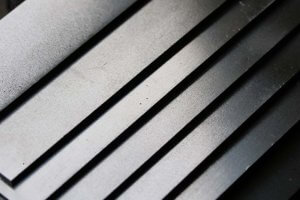
- Geometric Shape Error: The machined surface always deviates from its ideal smooth surface in the form of “peaks” and “valleys.” These deviations are categorized into macro and micro geometric shape errors.
- Macro Geometric Shape Error: The ratio of wavelength to wave height (L/H) is greater than 1000.
- Micro Geometric Shape Error (Surface Roughness): The ratio of wavelength to wave height (L/H) is less than 50.
- Surface Waviness: The ratio of wavelength to wave height (L/H) is between 50 and 1000.
- Physical-Mechanical and Chemical Properties of the Surface Layer Metal: This includes surface roughness, waviness, texture direction, scratches, plastic deformation, cutting heat, and residual stress.
Physical-Mechanical and Chemical Properties of the Surface Layer Metal
- Cold Work Hardening: The surface layer metal undergoes intense plastic deformation during machining, increasing the strength and hardness of the surface layer.
- Metallographic Structure Changes: Cutting heat causes changes in the metallographic structure of the surface layer, such as grinding burns.
- Residual Stress in the Surface Layer: The combined effect of cutting forces and cutting heat can result in residual compressive or tensile stress.
Impact of Machining Surface Quality on Part Performance
Impact on Wear Resistance
- Impact of Surface Roughness:
- Initial Wear Stage: Parts with larger surface roughness experience faster initial wear.
- Normal Wear Stage: When surface roughness is smaller, the wear resistance of parts improves.
- Severe Wear Stage: If the surface lubricant is squeezed out, the wear rate significantly increases.
- Impact of Roughness Profile Shape and Texture Direction:
- Under light load, when the texture directions of two surfaces align with the relative motion direction, the wear amount is smaller.
- With the same Ra value, a smooth profile has 3-4 times better wear resistance than a sharp profile.
- Impact of Surface Cold Work Layer and Residual Stress:
- Work hardening increases the strength of the surface layer, reducing plastic deformation and enhancing wear resistance.
- Residual compressive stress improves wear resistance, while tensile stress decreases it.
Impact on Fitting Accuracy
- Interference Fit:
- Greater roughness increases initial wear, enlarging the fit clearance and reducing fit accuracy.
- Clearance Fit:
- Greater roughness reduces the interference amount, weakening the joint strength of parts.
Impact on Fatigue Strength
- Surface Roughness: Rough surfaces are prone to stress concentration, leading to fatigue cracks.
- Residual Stress: Residual compressive stress delays fatigue crack initiation and propagation, enhancing fatigue strength.
Impact on Corrosion Resistance
- Surface Roughness: Greater roughness facilitates the accumulation of corrosive substances, intensifying penetration and corrosion.
- Residual Stress: Residual compressive stress enhances corrosion resistance, while tensile stress reduces it.
Process Factors Affecting Surface Roughness and Improvement Measures
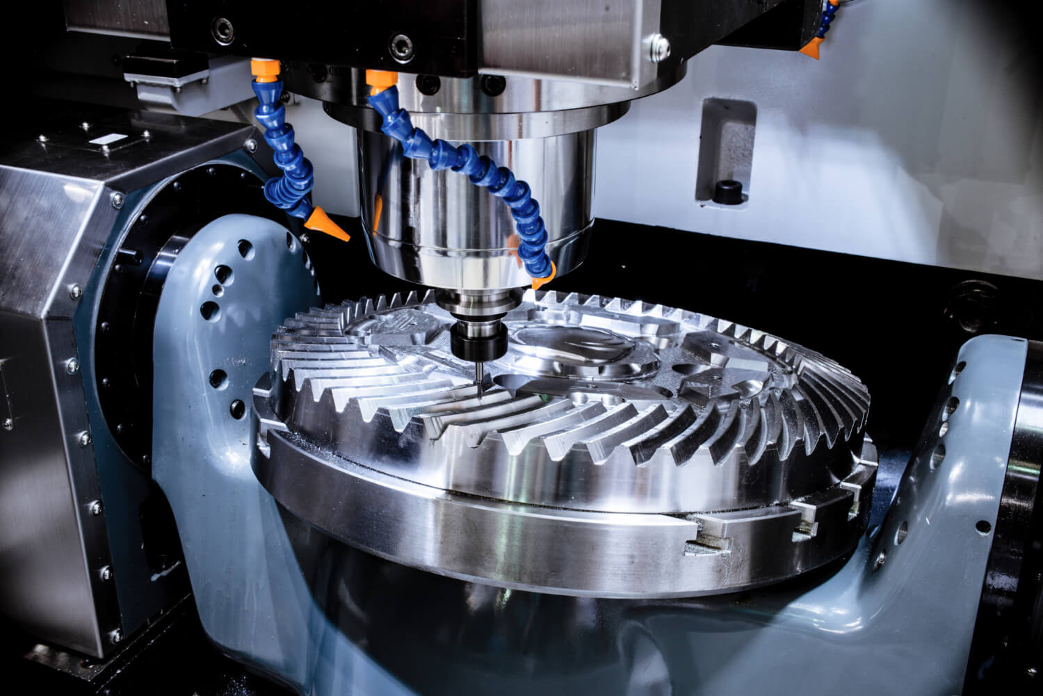
Geometric Factors
- Tool Geometric Parameters:
- The rake angle affects the degree of deformation in the cutting zone, chip morphology, and chip-breaking performance, thereby influencing roughness.
- Changes in the tool nose radius, main and auxiliary cutting edges, and relief angle affect the height of residual marks and thus the roughness.
- Cutting Parameters:
- Variations in cutting speed, depth of cut, and feed rate affect roughness.
Physical Factors
- Cutting Temperature: High cutting temperatures can cause changes in the metallographic structure, affecting surface quality.
- Cooling and Lubrication Effect: Good cooling and lubrication can reduce roughness.
Surface Roughness in Grinding
- Grinding Parameters: Changes in grinding speed, workpiece speed, and depth of cut affect roughness.
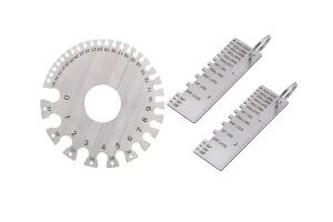
- Abrasive Grain Size: Finer abrasive grains result in lower roughness, but excessively fine grains can clog the wheel.
- Wheel Dressing: Dressing quality affects the cutting performance and roughness of the wheel.
- Workpiece Material: Material hardness and thermal conductivity influence roughness during grinding.
Measures to Improve the Physical-Mechanical Properties of the Surface Layer
- Surface Strengthening Processes: These processes use cold pressing methods to induce plastic deformation in the surface layer metal, increasing surface hardness and strength while generating residual compressive stress.
- Shot Peening: High-speed shots create a cold work layer and residual compressive stress, enhancing fatigue strength.
- Rolling: Pressure applied by rolling tools induces a cold work layer and residual compressive stress, improving surface hardness and fatigue strength.
- Liquid Abrasive Strengthening: High-speed liquid and abrasive mixtures reduce roughness and create residual compressive stress, enhancing wear and fatigue resistance.
Residual Stress in the Surface Layer
- Residual Stress from Cold Plastic Deformation: Plastic deformation in the surface layer is hindered by the underlying metal, creating residual compressive stress.
- Residual Stress from Thermal Plastic Deformation: Thermal expansion and contraction during cutting create residual tensile stress.
- Residual Stress from Metallographic Changes: Different metal structures have varying densities, causing residual stress due to metallographic changes during cutting.
Vibration in Machining and Its Impact
Hazards of Vibration
- Relative displacement between the workpiece and tool creates vibration marks, affecting surface quality and performance.
- Alternating loads on the system lead to tool and machine wear, hindering smooth machining.
- Vibration noise can harm the operator’s health.
Types of Vibration
- Forced Vibration: Caused and maintained by external periodic excitation forces.
- Self-Excited Vibration: A stable periodic vibration generated and maintained by alternating forces within the vibration system itself.
Causes of Forced Vibration
- External periodic excitation forces from sources such as other machines transmitted through the foundation to the machining machine.
- Unbalanced mass of high-speed rotating parts causing vibration.
- Defects in the transmission mechanism and inertia forces of reciprocating parts causing vibration.
- Intermittent cutting processes causing periodic changes in cutting forces.
Mathematical Description and Characteristics of Forced Vibration
Machining systems are multi-degree-of-freedom vibration systems with complex vibration modes. Simplifying the grinding system to a single-degree-of-freedom system can help analyze it, such as in the case of internal grinding head systems.
Self-Excited Vibration (Chatter)
- Conditions and Characteristics of Self-Excited Vibration:
- During cutting, strong relative vibration between the tool and workpiece can occur, known as self-excited vibration.
- Self-excited vibration systems form a closed-loop feedback control system where continuous energy is transformed into alternating forces that stimulate the vibration system.
- Characteristics of Self-Excited Vibration:
- The frequency of self-excited vibration is equal to or close to the natural frequency of the system.
- Self-excited vibration is triggered by an external excitation force and will not decay.
- Whether self-excited vibration is maintained depends on the balance of energy absorbed and consumed during each vibration cycle.
Vibration Control Measures
- Eliminating or Reducing Forced Vibration Conditions:
- Measure vibration frequency and reduce excitation forces.
- Adjust vibration source frequency to avoid resonance.
- Use isolation measures, such as elastic isolation devices.
- Eliminating or Reducing Self-Excited Vibration Conditions:
- Choose appropriate cutting parameters to reduce amplitude.
- Select appropriate tool geometric parameters to increase primary cutting edge and rake angle, reducing vibration.
- Increase cutting damping by reducing the tool’s relief angle or grinding a vibration damping edge on the back of the tool.
- Enhancing Vibration Resistance and Stability of the Machining System:
- Increase the rigidity of weak links in the machining system and reduce the mass of components to lower inertia.
- Increase system damping by using high-damping materials or adding friction damping to components.
- Using Various Vibration Dampening and Isolation Devices:
- Friction Dampers: Utilize solid or liquid friction damping to dissipate vibration energy.
- Dynamic Vibration Absorbers: Use additional mass to counteract excitation forces.
- Impact Dampers: Use free mass within a shell to repeatedly impact and dissipate vibration energy.
Through the rational selection and control of process parameters, combined with appropriate surface strengthening processes, significant improvements in machining surface quality can be achieved, thereby enhancing the performance and lifespan of parts.
Below is an example data table showing the work hardening effects of different machining methods on steel surfaces:
| Machining Method | Hardening Layer Depth (μm) | Hardening Degree (%) |
|---|---|---|
| Turning | 10-20 | 20-30 |
| Grinding | 5-10 | 15-25 |
| Rolling | 20-30 | 30-40 |
| Shot Peening | 30-50 | 35-45 |
By appropriately selecting and controlling process parameters and incorporating suitable surface strengthening processes, significant improvements in machining surface quality can be achieved, thereby enhancing the performance and lifespan of parts.
Other Articles You Might Enjoy
- Mechanical Machining Surface Quality: From Principles to Practical Application
Mechanical machining surface quality is a crucial aspect of mechanical manufacturing that directly impacts the performance and longevity of parts. This article will discuss the principles, influencing factors, and practical…
- How to solve surface roughness problems in cnc machining?
Introduction to CNC Machining and Surface Roughness Problems The process of Computer Numerical Control (CNC) machining plays a vital role in the manufacturing industry. This automated process uses computers to…
- The Role of Ceramic Beads in Achieving Superior Surface Quality in CNC Machining
Introduction to Ceramic Beads in CNC Machining Ceramic beads, known for their hardness and spherical uniformity, have emerged as a pivotal component in CNC machining operations aimed at achieving superior…
- Surface Refinement: Leveraging Bead Blasting for CNC Machining
In the realm of CNC machining, surface quality plays a pivotal role in determining the overall performance and aesthetics of the final product. Leveraging bead blasting as a surface refinement…
- The Dependable Quality Assurance in China CNC Machining
1. Introduction: Setting the Stage for Quality Excellence In this introductory section, we lay the groundwork for an exploration into the world of quality assurance in China CNC machining. We…
- Optimizing CNC Machining Parts Using Constant Surface Speed Techniques
CNC machining, particularly on lathes, can be a complex process, but understanding and utilizing constant surface speed (CSS) techniques can simplify and enhance the efficiency of your operations. The key…