Shaft Parts Machining
Function of Shaft Parts
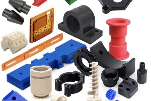
Shaft parts are primarily used to support transmission components and transmit torque. Common shaft parts include plain shafts, hollow shafts, half shafts, stepped shafts, spline shafts, cross shafts, eccentric shafts, screws, crankshafts, and camshafts.
Materials, Blanks, and Heat Treatment of Spindle Parts
Spindles commonly use materials such as 45 steel, with high-precision spindles using 40Cr, bearing steel GCr15, and spring steel 65Mn. For high-speed, heavy-load spindles, low carbon alloy steels such as 20CrMnTi and 20Mn2B are used. Blanks are often round bars and forgings, while large or complex shafts use castings. Heated forgings ensure metal fibers are evenly distributed along the surface, enhancing tensile, bending, and torsional strength.
Heat treatment processes include normalizing or annealing, quenching, and surface hardening to refine grains, relieve forging stress, reduce material hardness, and improve machinability. High-precision shafts also undergo low-temperature aging treatment.
Main Technical Requirements for Shaft Parts
- Dimensional Accuracy: Main surfaces are bearing journals (with IT 5
IT7 accuracy) and mating journals (with IT6IT9 accuracy). - Geometric Accuracy: Includes roundness, cylindricity, etc., with errors limited within dimensional tolerances.
- Positional Accuracy: Includes coaxiality, radial runout, etc.
- Surface Roughness: Bearing journals have 0.2
1.6μm roughness, while mating journals have 0.43.2μm. - Others: Heat treatment, chamfering, deburring, and appearance finishing requirements.
Clamping Methods for Shaft Parts
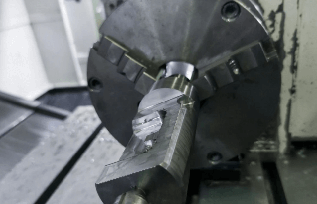
- Two Center Holes Positioning: The important outer cylindrical surface is used as the rough reference to machine the center hole, which then serves as the precise reference.
- Outer Surface Positioning: Suitable for hollow or short shafts.
- Plug or Drawbar Mandrel Positioning: Used for machining the outer surface of hollow shafts.
Key Requirements for CA6140 Spindle
- Bearing Journal: High accuracy affecting rotational precision.
- Morse Taper No.6: Used for installing centers or tool shanks, requiring coaxiality with the bearing journal axis.
- Tapered Surface and End Face: Locating surfaces for chuck or lathe fixtures.
- Thread: For fixing and adjusting spindle bearing clearance, requiring coaxiality with the bearing journal.
Machining Process for Lathe Spindle Parts
Process Flow Table
| No. | Process Name | Process Content | Locating Reference | Equipment |
|---|---|---|---|---|
| 1 | Material Preparation | Material preparation | ||
| 2 | Forging | Die forging | Vertical precision forge | |
| 3 | Heat Treatment | Normalizing | ||
| 4 | Sawing | Sawing | Saw machine | |
| 5 | Milling & Drilling | Milling end face and drilling center hole | Blank outer round | Center hole machine |
| 6 | Rough Turning | Rough turning outer round | Centers | Multi-tool semi-automatic lathe |
| 7 | Heat Treatment | Quenching | ||
| 8 | Large End Machining | Turning large end outer round, short taper, end face, step | Centers | Horizontal lathe |
| 9 | Small End Machining | Profiling small end outer round | Centers | Profiling lathe |
| 10 | Deep Hole Drilling | Drilling φ48mm through hole | Both ends bearing journals | Deep hole drill |
| 11 | Small End Tapering | Turning small end taper (1:20 taper plug, contact rate ≥50%) | Both ends bearing journals | Horizontal lathe |
| 12 | Large End Tapering | Turning large end taper (Morse No.6 taper plug, contact rate ≥30%), short taper, end face | Both ends bearing journals | Horizontal lathe |
| 13 | Drilling | Drilling holes on the large end face | Large end inner taper | Radial drill |
| 14 | Heat Treatment | Local high-frequency quenching (φ90g5, short taper, Morse No.6 taper hole) | Centers | High-frequency quenching equipment |
| 15 | Precision Turning | Precision turning all outer rounds, slotting, chamfering | Centers | CNC lathe |
| 16 | Rough Grinding | Rough grinding φ75h5, φ90g5, φ100h7 outer rounds | Plug centers | Combined cylindrical grinder |
| 17 | Rough Grinding Taper | Rough grinding large end inner taper (Morse No.6 taper plug, contact rate ≥40%) | Front bearing journal and φ75h5 outer round | Internal grinder |
| 18 | Spline Milling | Milling φ89f6 spline | Plug centers | Spline milling machine |
| 19 | Key Slot Milling | Milling 12f9 key slot | φ80h5 and M115mm outer round | Vertical milling machine |
| 20 | Thread Turning | Turning three threads (matching nuts) | Plug centers | Horizontal lathe |
| 21 | Precision Grinding | Precision grinding all outer rounds and ends | Plug centers | Cylindrical grinder |
| 22 | Rough Grinding Cones | Rough grinding 1:12 outer cones | Plug centers | Special combined grinder |
| 23 | Precision Grinding Cones | Precision grinding 1:12 outer cones, D end face, short taper | Plug centers | Special combined grinder |
| 24 | Precision Grinding Taper | Precision grinding Morse No.6 inner taper (remove plug, contact rate ≥70%) | Front bearing journal and φ75h5 outer round | Special spindle taper grinder |
| 25 | Deburring | Deburring, chamfering end holes | Handwork | |
| 26 | Inspection | Full inspection according to drawings | Front bearing journal and φ75h5 outer round | Special gauge |
Key Points and Process Analysis
- Division of Processing Stages: Rough and finish machining are separated, following the principle of “rough before finish.” Important surfaces (especially bearing journals) are processed as the main line, interspersed with other surface processing steps.
- Selection of Locating References: Using two center holes as the locating reference; positioning with bearing journals for taper turning; using plug center holes for rough and precision grinding outer rounds; positioning with outer rounds for rough grinding tapers; final taper grinding with bearing journals as reference.
- Arrangement of Process Sequence: Center drilling first, deep hole drilling before semi-finish turning the outer round, secondary surfaces processing after finish turning or rough grinding the outer round.
- Main Process Methods: Center hole processing, outer round processing, spline processing, precision taper grinding.
Spindle Inspection
- In-process Inspection: Using automatic measurement devices to control the machining process based on measurement results without interrupting processing.
- Post-process Inspection: Dimensional accuracy with external micrometers, high-volume production using smooth limit gauges, surface roughness with roughness samples, high precision using optical instruments.
Bracket and Box Parts Machining
Function of Bracket and Box Parts
Box parts are foundational components of machines, connecting relevant parts such as shafts, sleeves, and gears into an integral whole, maintaining their correct relative positions, transmitting torque, or altering speed to complete specified movements.
Materials and Blanks for Box Parts
Box parts are commonly made of gray cast iron, with aluminum alloy used for car and motorcycle crankcases. Cast blanks are often used, and post-casting artificial aging or annealing is required to reduce residual stress.
Process Analysis
- Selection of Rough References: Usually, important holes and another hole spaced apart are used as rough references to ensure uniform machining allowance.
- Selection of Precision References: Assembly references or specially machined surfaces and two holes are often used to ensure consistency.
- Process Concentration and Priority: High precision positional requirements are concentrated in the same process to minimize clamping times and ensure precision.
Hole Series Machining
Box parts have various hole series, including parallel holes, coaxial holes, and intersecting holes. Methods include using previously machined holes for guidance, boring machine rear column guide sleeves, and flip boring.
Box Inspection
- Surface Roughness Inspection: Visual or sample comparison, optical instruments for small Ra values.
- Dimensional Accuracy Inspection: Plug gauges for high-volume production, internal micrometers or pneumatic gauges for high precision.
- Flatness and Straightness Inspection: Flat rulers, thickness gauges, autocollimators, or level instruments.
- Coaxiality Inspection: Using test rods.
- Hole Spacing and Parallelism Inspection: Vernier calipers or micrometers, coordinate measuring machines for high precision.
Bracket Machining Example
| No. | Process Name | Process Content | Type | Equipment |
|---|---|---|---|---|
| 1 | Casting | Casting blank | ||
| 2 | Heat Treatment | Annealing | ||
| 3 | Marking | Marking center lines and processing lines | Handwork | Marking table |
| 4 | Planing | Planing bottom surface | Shaper | |
| 5 | Turning | Drilling and boring bearing holes, turning end faces | Lathe | |
| 6 | Handwork | Marking bearing hole lines | ||
| 7 | Handwork | Drilling screw holes and countersinking protrusions | Drill press | |
| 8 | Inspection | Inspection according to drawings |
Box Machining Example
| No. | Process Name | Process Content | Type | Equipment |
|---|---|---|---|---|
| 1 | Casting | Casting blank | ||
| 2 | Heat Treatment | Artificial aging | ||
| 3 | Painting | Primer painting | ||
| 4 | Marking | Marking center lines, connecting holes, pins, screw holes | Marking table | |
| 5 | Planing | Rough and finish planing fitting surfaces and top surface | Shaper | |
| 6 | Marking | Marking according to processing surface | Marking table | |
| 7 | Drilling | Drilling connecting holes, screw holes | Radial drill | |
| 8 | Handwork | Tapping threads, scraping fitting surfaces, assembling | ||
| 9 | Milling | Rough and finish milling bearing hole end surfaces | End mill | |
| 10 | Boring | Rough and finish boring bearing holes | Horizontal borer | |
| 11 | Handwork | Deburring, cleaning, marking | ||
| 12 | Painting | Painting non-machined surfaces | ||
| 13 | Inspection | Full inspection according to drawings |
Cylindrical Gear Machining
Gear Structure and Classification
Gears are classified based on structure and application, including spur gears, helical gears, herringbone gears, spiral gears, internal gears, etc.
Gear Accuracy Requirements
- Motion Accuracy: Ensure precise motion transmission and constant transmission ratio, with maximum angle error not exceeding specified limits.
- Smooth Operation: Ensure smooth transmission with minimal vibration, impact, and noise.
- Contact Accuracy: Ensure uniform load distribution during transmission to prevent premature wear or breakage.
- Backlash: Ensure proper clearance for thermal expansion, elastic deformation, and assembly errors, facilitating lubrication and oil film formation.
Gear Materials and Heat Treatment
Gear materials are selected based on usage requirements and working conditions. Common materials include medium carbon steel, medium carbon alloy steel, low carbon alloy steel, and cast steel. Gear blanks are chosen based on material, shape, size, usage conditions, and production volume, commonly including cast iron, bar stock, forgings, and cast steel blanks.
Gear Machining Methods
Gear machining methods are divided into forming methods and generating methods. Forming methods include gear milling, gear shaping, and forming gear grinding, while generating methods include gear hobbing, gear shaping, gear shaving, gear grinding, and gear honing. The machining process is divided into forming the gear blank, rough machining, semi-finish machining, heat treatment, and finish machining.
Gear Machining Process Flow Table
| No. | Process Name | Process Content | Locating Reference |
|---|---|---|---|
| 1 | Forging | Forging blanks | |
| 2 | Heat Treatment | Normalizing | |
| 3 | Rough Turning | Rough turning shape, leaving allowance | |
| 4 | Finish Turning | Finish turning, leaving grinding allowance | Outer and end face |
| 5 | Gear Hobbing | Hobbing gear teeth, leaving grinding allowance | Inner hole and end face A |
| 6 | Chamfering | Chamfering to size | Inner hole and end face A |
| 7 | Deburring | Deburring | |
| 8 | Heat Treatment | Surface hardening | Gear teeth |
| 9 | Key Slotting | Slotting keyways to size | Inner hole and end face A |
| 10 | Grinding Surface | Grinding flat surfaces | Inner hole and end face A |
| 11 | Grinding Bore | Grinding bore to size | Inner hole and end face A |
| 12 | Gear Grinding | Grinding gear teeth | Inner hole and end face A |
| 13 | Inspection | Full inspection according to drawings |
Gear Blank Machining
Gear blank machining is crucial, as it establishes the reference for gear tooth machining and inspection. Gear tooth measurements are based on the pitch circle diameter, and accurate pitch circle diameter is essential for correct tooth thickness measurement.
Gear End Machining
Gear end machining includes rounding, chamfering, deburring, and de-burring. Rounded or chamfered gear teeth facilitate meshing, reducing impact. Chamfering removes sharp edges and burrs. End machining is usually performed after gear hobbing or shaping and before gear shaving.
Sleeve Parts Machining
Structure and Classification of Sleeve Parts
Sleeve parts support or guide movement, such as cylinder liners, oil cylinders, drill sleeves, and sliding bearings. Sleeve parts are relatively simple but difficult to machine, requiring high geometric and positional accuracy.
Blanks and Materials for Sleeve Parts
Sleeve parts blanks are often cast or forged with holes, and materials include steel, cast iron, bronze, brass, high-quality alloy steel, and Babbitt alloy. Sliding bearings often use copper and high-quality alloy steel for high strength and hardness requirements.
Machining Methods for Sleeve Parts
Machining sleeve parts requires ensuring the coaxiality of the inner and outer diameters and perpendicularity of the end face to the axis. Basic methods include drilling, reaming, boring, honing, and cold extrusion.
Sleeve Parts Machining Process Flow Table
| No. | Process Name | Process Content | Equipment |
|---|---|---|---|
| 1 | Material Cutting | Cutting material | Saw machine |
| 2 | Rough Turning | Turning end face, drilling through hole | Lathe |
| 3 | Semi-finish Turning | Semi-finish turning outer diameter | Lathe |
| 4 | Heat Treatment | Ensuring carburizing depth 0.8-1.2mm, hardness HRC58-62 | |
| 5 | Grinding Inner/Outer | Grinding outer diameter, inner bore | Universal grinder |
| 6 | Honing Inner Bore | Honing inner bore to size, grinding arc | Lathe |
| 7 | Inspection | Inspection according to drawings |
Key Points
- Reducing Cutting Force and Heat: Separate rough and finish machining, sufficient cooling and lubrication during machining.
- Reducing Clamping Force: Change radial clamping to axial clamping, use transition sleeves or spring sleeves for even radial clamping.
Connecting Rod Machining
Structure, Materials, and Requirements of Connecting Rods
Connecting rods transmit motion and force, subjected to significant dynamic loads. Medium and large connecting rods consist of a rod body and a rod cap, made from 45 steel or 40Cr, 45Mn2, and increasingly ductile iron. The blank is forged.
Connecting Rod Machining Process Flow Table
| No. | Process Name | Process Content | Equipment | Locating Reference |
|---|---|---|---|---|
| 1 | Forging | Forging blanks | ||
| 2 | Heat Treatment | Quenching | ||
| 3 | Magnetic Inspection | Magnetic inspection | ||
| 4 | Rough & Finish Milling | Rough and finish milling fitting surfaces | Planar grinder | |
| 5 | Rough & Finish Milling | Rough and finish milling both surfaces | Vertical milling machine | End face |
| 6 | Grinding Fitting Surface | Grinding fitting surfaces | Multi-station special machine | Large and small end face |
| 7 | Drilling & Reaming | Drilling and reaming small end hole, chamfering | Large and small end face | |
| 8 | Rough & Finish Milling | Rough and finish milling fitting surfaces | Large and small end face | |
| 9 | Drilling & Reaming | Drilling and reaming positioning holes | Small end hole and end face | |
| 10 | Tapping & Drilling | Tapping and drilling screw holes | Positioning holes | |
| 11 | Drilling & Counterboring | Drilling and counterboring screw holes | Positioning holes | |
| 12 | Cleaning | Cleaning | ||
| 13 | Inspection | Inspection according to drawings | ||
| 14 | Demagnetization | Demagnetization |
Connecting Rod Process Arrangement
The sequence includes rough milling, fine grinding end surfaces, drilling and reaming small end holes, rough and finish milling fitting surfaces, half round hole and joint boring large end holes, grinding fitting surfaces, drilling and reaming positioning holes, fitting assembly, grinding assembly end surfaces, semi-finish boring large end holes, fine boring large and small end holes, drilling small oil holes, chamfering, honing large end holes, pressing small end bushings, milling small end hole end surfaces, fine boring small end bushings, disassembling assembly and numbering, milling bearing positioning grooves, aligning assembly, demagnetization, cleaning, and inspection.
Connecting Rod Inspection
- Positional Accuracy: Checking parallelism of large and small end hole axes.
- Flaw Detection: Inspecting for internal quality using flaw detection methods.
Other Articles You Might Enjoy
- Precision CNC Machining for High-Performance Industrial Machinery
Precision CNC Machining for High-Performance Industrial Machinery The process of Precision CNC (Computer Numerical Control) machining is at the core of manufacturing high-performance industrial machinery. This technique leverages a computer's…
- Precision Aluminum Machining for Aerospace: Custom CNC Services
Precision Aluminum Machining for Aerospace: Custom CNC Services In the world of manufacturing, precision aluminum machining plays a pivotal role, particularly in aerospace industries where superior precision is required. As…
- CNC Machining for Medical Applications: Compliance and Material Selection?
Introduction to CNC Machining in Medical Applications CNC or Computer Numerical Control machining is a manufacturing process wherein pre-programmed computer software dictates the movement of factory tools and machinery. This…
- Introduction to Precision Parts Machining: Cutting and Special Processes
Precision parts cutting machining primarily includes precision turning, mirror grinding, and lapping. Using finely ground single-crystal diamond tools on precision lathes, ultra-fine turning is performed with a cutting thickness of…
- Why should I choose CNC multi-axis machining in China? What are the advantages?
I usually choose Chinese CNC machining factories when I need to custom manufacture parts in large quantities. These factories not only have advanced technology and equipment but also provide high-quality…
- CNC Machining: Metals, Processes and More( rivets Dolores)
In the world of CNC (Computer Numerical Control) machining, various materials are used depending on the type of product being produced. Two such commonly used metals are aluminum and titanium.…