When producing CNC machining parts, it’s not just about hitting the right dimensions and achieving the desired surface roughness. The shape and the relative positions of different elements of a part can also present challenges. Let’s dive into the world of shape and position tolerances, which are crucial for ensuring that parts fit and function correctly.
Shape and Position Errors
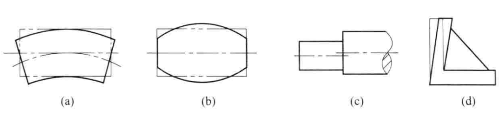
During production, parts can exhibit shape errors, as shown in Figures (a) and (b), and position errors, as depicted in Figures (c) and (d). Shape errors refer to deviations from the ideal shape, while position errors involve deviations from the ideal location.
These errors can significantly affect the interchangeability of parts and the overall performance and lifespan of machines. Hence, controlling these errors is crucial for quality assurance.
Key Terminologies
- Element: These are the points, lines, and surfaces that make up the geometric features of a part. Points include center points of spheres and axes of cylinders; lines include center lines and axis lines; surfaces include planes and curved surfaces.
- Ideal Element: This is the theoretically perfect geometric shape used as a reference during design.
- Actual Element: The element that actually exists on the part, which may have deviations due to manufacturing processes.
- Measured Element: The element on which shape or position tolerance is specified.
- Datum Element: The element used as a reference for determining the direction or position of the measured element.
Shape and Position Tolerances
Shape tolerance refers to the allowable variation in the shape of an element, while position tolerance refers to the allowable variation in the location of an element relative to a datum. These tolerances are critical for ensuring that parts can be assembled and function correctly.
Examples:
- Straightness: For a shaft, the straightness tolerance might be specified to ensure the shaft’s surface does not deviate beyond a certain limit.
- Flatness: For a part’s surface, flatness tolerance ensures the surface remains within two parallel planes a specific distance apart.
Here are some symbols used for different types of shape and position tolerances:
| Tolerance Type | Symbol | Example Description |
|---|---|---|
| Straightness | ———— | A shaft’s straightness must be within 0.02mm. |
| Flatness | □ | A surface’s flatness must be within 0.1mm. |
| Roundness | ⃝ | The roundness of a hole must be within 0.05mm. |
| Cylindricity | ⦿ | The cylindricity of a cylinder must be within 0.1mm. |
| Parallelism | ∥ | A surface must be parallel to a datum within 0.05mm. |
| Perpendicularity | ⊥ | A hole must be perpendicular to a surface within 0.05mm. |
| Position | ○ | The position of a hole relative to a datum within 0.1mm. |
Practical Application
In practical terms, managing these tolerances involves careful planning and precise measurement. For example, ensuring that the flatness of a surface is within the specified tolerance might require specific machining techniques and the use of precise measuring tools.
Example Table of Achievable Tolerances:
To provide a comprehensive understanding of the achievable tolerances across various machining processes, here is an table that includes a broader range of processes and the typical tolerances they can achieve.
| Machining Process | Straightness | Flatness | Roundness | Cylindricity | Parallelism | Perpendicularity | Position | Concentricity | Surface Roughness (Ra) |
|---|---|---|---|---|---|---|---|---|---|
| Grinding | 0.001 – 0.005 mm | 0.002 mm | 0.002 mm | 0.003 mm | 0.002 mm | 0.003 mm | 0.003 mm | 0.003 mm | 0.1 – 0.2 µm |
| Milling | 0.01 – 0.03 mm | 0.02 mm | 0.02 mm | 0.03 mm | 0.02 mm | 0.03 mm | 0.03 mm | 0.03 mm | 0.4 – 1.6 µm |
| Turning | 0.01 – 0.02 mm | 0.02 mm | 0.01 mm | 0.02 mm | 0.02 mm | 0.02 mm | 0.02 mm | 0.02 mm | 0.8 – 1.6 µm |
| Drilling | 0.02 – 0.05 mm | 0.03 mm | 0.03 mm | 0.04 mm | 0.03 mm | 0.04 mm | 0.04 mm | 0.04 mm | 1.6 – 3.2 µm |
| Boring | 0.005 – 0.02 mm | 0.01 mm | 0.005 mm | 0.01 mm | 0.01 mm | 0.015 mm | 0.015 mm | 0.015 mm | 0.4 – 1.6 µm |
| Honing | 0.002 – 0.005 mm | 0.002 mm | 0.001 mm | 0.003 mm | 0.002 mm | 0.002 mm | 0.003 mm | 0.003 mm | 0.1 – 0.4 µm |
| Lapping | 0.001 – 0.003 mm | 0.001 mm | 0.001 mm | 0.002 mm | 0.001 mm | 0.0015 mm | 0.002 mm | 0.002 mm | 0.05 – 0.2 µm |
| Electrical Discharge Machining (EDM) | 0.01 – 0.02 mm | 0.01 mm | 0.01 mm | 0.02 mm | 0.01 mm | 0.015 mm | 0.015 mm | 0.015 mm | 0.8 – 1.6 µm |
| Laser Cutting | 0.02 – 0.05 mm | 0.03 mm | 0.03 mm | 0.04 mm | 0.03 mm | 0.04 mm | 0.04 mm | 0.04 mm | 1.6 – 3.2 µm |
| Water Jet Cutting | 0.05 – 0.1 mm | 0.07 mm | 0.07 mm | 0.08 mm | 0.07 mm | 0.08 mm | 0.08 mm | 0.08 mm | 3.2 – 6.3 µm |
| Additive Manufacturing (3D Printing) | 0.1 – 0.2 mm | 0.1 mm | 0.1 mm | 0.15 mm | 0.1 mm | 0.15 mm | 0.15 mm | 0.15 mm | 6.3 – 12.5 µm |
This table provides a more detailed overview of the achievable tolerances across various machining processes, offering a comprehensive reference for designers and machinists to understand the capabilities and limitations of different methods.
Understanding and applying these tolerances is essential for producing high-quality CNC machined parts that meet design specifications and perform reliably in their intended applications.