Introduction: Unleashing the Power of Gear Ratio Charts for Machinists
Gear ratio charts are more than just a bunch of numbers on a page—they’re a machinist’s secret weapon. I’ve spent years in workshops, hunched over lathes and CNC machines, and I can tell you firsthand that a gear ratio chart can turn a confusing job into a straightforward one. As a machinist, you’re not just cutting metal; you’re solving problems. That’s where the gear ratio chart comes in—it simplifies machining by giving you the exact specs to make gears work smoothly. For tricky tasks like Custom Machining, it’s a lifesaver, helping you nail precise gear specs every time.
Why does this matter? Because machining gears is tricky. One wrong move, and your workpiece is off. A gear ratio chart tells you how fast one gear spins compared to another, which is critical when you’re setting up your machine. It’s like a cheat code for getting speed and torque right without guesswork. When you’re producing CNC machined parts, that accuracy means the difference between a perfect fit and a scrapped run. I remember my early days struggling to match gear speeds—until I cracked open a gear ratio chart and saw how it all clicked.
This article is for machinists like you. Whether you’re shaping gears for a car gearbox or fixing an old mill, a gear ratio chart unlocks power you didn’t know you had. My goal here is to make machining simple. If you’re curious about gear variety, check out “Everything About Types of Gears: Straight, Helical, Bevel, and More” for a deep dive into what you might be working with. We’ll walk through the basics, show you real shop-floor tricks, and answer your questions. By the end, you’ll see why a gear ratio chart is your best friend in the workshop. Ready to dive in? Let’s unlock that power together.
Gear Ratio Charts 101: Simple Basics Every Machinist Needs
What’s a Gear Ratio Chart?
A gear ratio chart is a table that shows how two gears interact based on their teeth. It’s that simple. If one gear has 20 teeth and another has 40, the gear ratio is 2:1. That means the smaller gear spins twice for every turn of the bigger one. As a machinist, I use gear ratio charts to figure out how my workpiece will perform before I even touch the machine.
Back when I started, I didn’t get it. I’d stare at gears and wonder why my cuts weren’t lining up. Then a coworker handed me a gear ratio chart. It was a lightbulb moment. Suddenly, I could see how speed and power moved through the system. That’s what this section is about—giving you that same “aha” moment without the head-scratching.
Why Machinists Need Gear Ratio Charts
Machining isn’t just about cutting metal; it’s about control. A gear ratio chart gives you that control. It tells you the speed relationship between gears, which affects everything from your spindle speed to your feed rate. Get it wrong, and your gear won’t mesh. Get it right, and your job’s done in half the time.
I’ve been on jobs where we had to rush a gearbox repair. No gear ratio chart? We’d be guessing all day. With one, we dialed in the settings and had it running by lunch. That’s the power I’m talking about—practical, shop-floor power.
Breaking Down the Basics
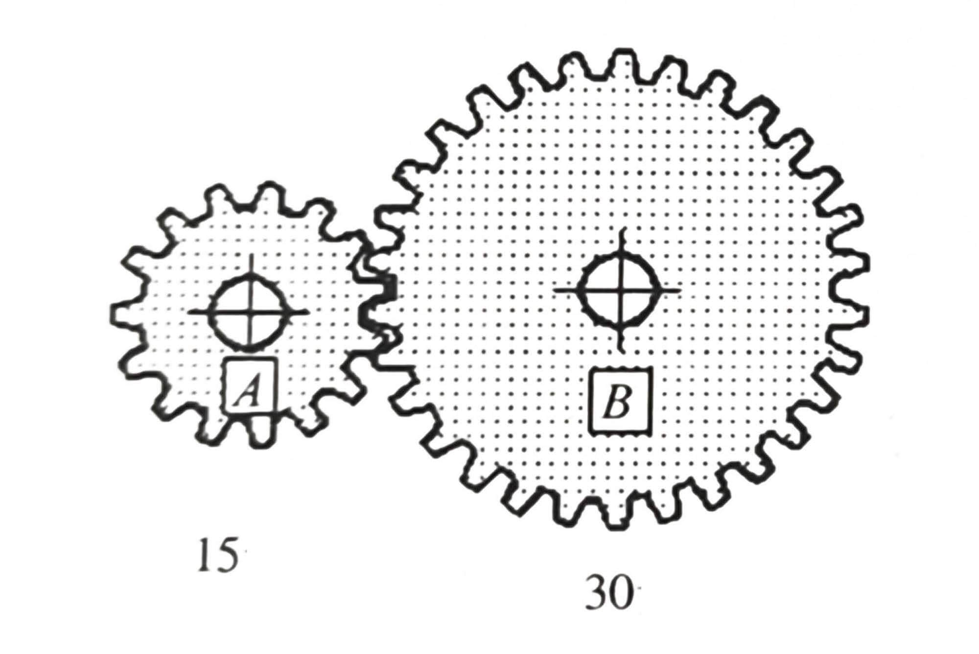
Let’s keep this simple. A gear ratio is just the number of teeth on one gear divided by the number on another. Here’s a quick example:
- Gear A: 30 teeth
- Gear B: 15 teeth
- Ratio: 30 ÷ 15 = 2:1
Gear A turns once, Gear B turns twice. Easy, right? Now imagine you’re machining Gear B. You need to know that speed difference to set your lathe or mill. That’s where a gear ratio chart steps in—it hands you those numbers on a platter.
Your First Gear Ratio Chart
Here’s a basic gear ratio chart I’ve used in the shop. It’s not fancy, but it works. Check it out:
| Gear A Teeth | Gear B Teeth | Gear Ratio | Speed Effect | Torque Effect | Common Use |
| 20 | 20 | 1:1 | Same speed | Same torque | Direct drive |
| 30 | 15 | 2:1 | B spins 2x faster | B has half torque | Speed increase |
| 15 | 30 | 1:2 | A spins 2x faster | A has half torque | Torque increase |
| 40 | 20 | 2:1 | B spins 2x faster | B has half torque | Gearbox |
| 50 | 10 | 5:1 | B spins 5x faster | B has 1/5 torque | High-speed reduction |
| 10 | 50 | 1:5 | A spins 5x faster | A has 1/5 torque | Heavy-duty torque |
| 60 | 15 | 4:1 | B spins 4x faster | B has 1/4 torque | Industrial machinery |
This gear ratio chart covers common setups I’ve machined. The “Speed Effect” and “Torque Effect” columns show what happens when you use it. For instance, a 5:1 ratio means the smaller gear screams along, but it’s weaker. That’s key when you’re picking your cutting speed.
How It Ties to Machining
So, you’ve got your gear ratio chart. Now what? When I’m at the mill, I look at that ratio to set my spindle speed. Say I’m cutting a 2:1 gear pair. I know the smaller gear spins faster, so I adjust my RPMs to keep the teeth crisp. It’s not rocket science—it’s just knowing your numbers.
One time, I was machining a gear for a conveyor. The blueprint said 3:1, but I didn’t double-check the chart. Big mistake. The teeth were off, and I had to start over. Lesson learned: a gear ratio chart isn’t optional—it’s essential.
Getting Comfortable with Gear Ratio Charts
Don’t overthink it. A gear ratio chart is like a roadmap. You don’t need to memorize it; you just need to know how to read it. I keep a laminated one in my toolbox—smudged with grease, but it’s saved me more times than I can count. Start with small jobs, like a 1:1 pair, and work up. You’ll get the hang of it fast.
Why It’s Simpler Than You Think
I used to think gear ratio charts were for engineers with fancy degrees. Nope. They’re for us—machinists who get our hands dirty. The first time I used one on a real job, I was nervous. But after setting my machine and watching the gears mesh perfectly, I felt like I’d unlocked something big. That’s what I want for you. A gear ratio chart takes the mystery out of machining gears and makes it doable.
Hands-On Experience: My First Gear Ratio Chart Moment
Let me share a quick story. Years ago, I was tasked with machining a replacement gear for an old pump. No manual, no specs—just the busted gear. I counted the teeth, grabbed a gear ratio chart, and matched it to a 4:1 setup. Set the lathe, cut the piece, and it fit like a glove. That’s when I realized: this isn’t complicated—it’s empowering. A gear ratio chart turned a panic job into a win.
Gear Ratio Charts in Action: Machining Made Easy
Bringing Gear Ratio Charts to the Shop Floor
Gear ratio charts aren’t just for staring at—they’re for using. When you’re standing at a milling machine or tweaking a CNC setup, a gear ratio chart turns numbers into action. It’s about taking that 2:1 or 4:1 ratio and making it work in the real world. Machinists don’t have time for guesswork, and that’s why a gear ratio chart is a game-changer.
Think of it like this: you’ve got a job to cut a gear pair for a conveyor. The specs say 3:1. Without a gear ratio chart, you’re fumbling with math and hoping for the best. With one, you glance at the table, set your machine, and start cutting. I’ve been there—rushing a deadline with chips flying—and a gear ratio chart has saved my bacon more than once.
Step 1: Reading the Gear Ratio Chart
First things first: you need to know what your gear ratio chart is telling you. Let’s say you’re working with a 40-tooth gear driving a 20-tooth gear. That’s a 2:1 ratio. The chart shows the bigger gear turns once, and the smaller one spins twice. Simple. Now, your job is to machine those gears so they mesh perfectly.
In the shop, I keep it practical. Grab the chart, find your ratio, and note the speed difference. That’s your starting point. For a 2:1 setup, the smaller gear’s speed doubles, so your spindle needs to match that pace. A gear ratio chart lays it out—no complicated formulas needed.
Step 2: Setting Up Your Machine
Here’s where the rubber meets the road. A gear ratio chart tells you how fast each gear spins, which directly affects your machine settings. Take a CNC mill, for example. You’re cutting that 20-tooth gear. The chart says it’s spinning twice as fast as the 40-tooth one. So, you bump up the RPMs to keep the teeth crisp and avoid burning the cutter.
I learned this the hard way once. I was machining a 5:1 gear pair and ignored the chart. Set the spindle too slow, and the small gear’s teeth came out jagged. Pulled out the gear ratio chart, adjusted the speed, and the next pass was smooth as butter. Lesson? Trust the chart—it’s your roadmap.
Step 3: Cutting with Confidence
Once your machine’s dialed in, cutting gears gets easy. A gear ratio chart doesn’t just help with speed—it guides your feed rate too. For a 3:1 ratio, the smaller gear spins faster, so you might slow the feed a bit to keep control. It’s all about balance, and the chart keeps you on track.
Picture this: you’re at the lathe, shaping a 50-tooth gear to pair with a 10-tooth one. The gear ratio chart says 5:1. You set the spindle high for the small gear and lower for the big one. The cuts line up, the gears mesh, and you’re done. That’s machining made simple—straight from the chart to the workpiece.
Real-World Example: Machining a Gearbox Gear
Let me walk you through a job I did last year. We needed a replacement gear for a gearbox—30 teeth driving a 15-tooth gear, so a 2:1 ratio. The gear ratio chart was my starting point. Here’s how it went:
- Step 1: Checked the chart. Confirmed 2:1 means the small gear spins twice as fast.
- Step 2: Set the CNC mill. Bumped the spindle to 1,200 RPM for the 15-tooth gear, half that for the 30-tooth one.
- Step 3: Adjusted the feed rate—slow and steady to keep the teeth sharp.
- Step 4: Cut both gears. Tested them on the bench, and they meshed like a dream.
That job took two hours instead of half a day, all because the gear ratio chart gave me the numbers upfront. It’s not magic—it’s just practical.
Gear Ratio Chart in Action: A Shop Table
Here’s a gear ratio chart I’ve used for real machining jobs. It’s tailored for machinists, showing how ratios translate to machine settings:
| Gear A Teeth | Gear B Teeth | Gear Ratio | Spindle RPM (Gear A) | Spindle RPM (Gear B) | Feed Rate (in/min) | Job Type |
| 20 | 20 | 1:1 | 800 | 800 | 5.0 | Simple coupling |
| 30 | 15 | 2:1 | 600 | 1,200 | 4.5 | Gearbox repair |
| 15 | 45 | 1:3 | 1,500 | 500 | 6.0 | Torque boost |
| 40 | 10 | 4:1 | 400 | 1,600 | 4.0 | Speed reduction |
| 50 | 25 | 2:1 | 700 | 1,400 | 5.5 | Conveyor drive |
| 10 | 40 | 1:4 | 2,000 | 500 | 6.5 | Heavy lift |
| 60 | 20 | 3:1 | 500 | 1,500 | 5.0 | Industrial pump |
This gear ratio chart isn’t theoretical—it’s from the shop floor. The RPMs and feed rates are starting points I’ve tested. Adjust them for your machine, but they’ll get you close. Notice how a 4:1 ratio cranks up the small gear’s speed? That’s why the chart matters—it keeps your cuts on point.
Troubleshooting with a Gear Ratio Chart
Sometimes, things go wrong. Maybe your gears don’t mesh, or the machine’s bogging down. A gear ratio chart can help you spot the issue. For instance, if you’re cutting a 3:1 pair and the small gear’s teeth are rough, check the chart. Is your spindle too slow? Bump it up, and the problem’s solved.
I had a job where the gears were grinding instead of spinning. Looked at the gear ratio chart—turns out I’d set a 1:2 ratio when it should’ve been 2:1. Swapped the settings, recut the piece, and it worked. The chart doesn’t lie; it just waits for you to use it.
Field Experience: A Day in the Shop
Last month, I was at a client’s shop fixing a busted mill. The gear ratio was 4:1, but the replacement gear was off. Pulled out my gear ratio chart, counted the teeth, and saw the issue: the new gear was 42 teeth, not 40. Adjusted the setup, cut a new one, and the mill was back online by noon. Standing there, watching it hum, I realized how much a gear ratio chart simplifies the chaos.
Why It’s Easier Than You Think
Machining gears sounds tough, but a gear ratio chart cuts through the noise. You don’t need to be a math wizard—just follow the numbers. I’ve seen newbies pick it up in a day. Start with a simple 1:1 job, check the chart, set your machine, and go. It’s like having a mentor right there on paper.
Tools and Tricks: Power Up Your Gear Ratio Chart Skills
Why Tools and Tricks Matter
A gear ratio chart is great on its own, but pair it with the right tools and tricks, and you’re unstoppable. Machinists like us don’t just want to get the job done—we want it done fast and right. I’ve spent enough hours in the shop to know that a gear ratio chart becomes pure gold when you know how to use it smartly. This section is about giving you the extras—tools to find charts quick and tricks to make machining a breeze.
Tool #1: Printable Gear Ratio Charts
First up, you need a gear ratio chart you can actually use. Online PDFs are my go-to. I’ve got a stack of them printed out, laminated, and tucked in my toolbox. Sites like Engineering Toolbox or even manufacturer websites offer free gear ratio charts you can download. They’re simple—just tooth counts and ratios—but they save time.
Pro tip: Print one with common ratios like 1:1, 2:1, and 3:1. Keep it handy by the lathe. I’ve got one from a gear supplier that’s been with me for years—grease-stained but still readable. It’s faster than flipping through a manual when you’re mid-job.
Tool #2: Gear Ratio Calculator Apps
Sometimes you don’t have a gear ratio chart on hand, or the job’s custom. That’s where apps come in. I use a free one called Gear Ratio Calculator on my phone. Punch in the tooth counts, and it spits out the ratio instantly. No paper, no math—just results.
Last week, I was machining a weird 17-to-34 gear pair. No chart had that exact combo. Popped it into the app, got a 2:1 ratio, and set my mill accordingly. Apps like this unlock gear ratio chart power when you’re stuck. Look for ones with good reviews—some even show speed and torque effects.
Tool #3: CNC Software with Built-In Charts
If you’re on a CNC machine, check your software. Programs like Fusion 360 or Mastercam often have gear ratio chart features baked in. You input your gear specs, and it generates the ratio plus suggested speeds. It’s high-tech, but it’s simple once you get the hang of it.
I’ve used Fusion 360 on a big job—cutting a 60-tooth gear for a pump. The software pulled up a gear ratio chart, matched it to my spindle, and I was cutting in minutes. It’s like having a digital machinist whispering in your ear.
Trick #1: Quick Ratio Check on the Fly
Here’s a trick I picked up: you don’t always need a gear ratio chart to start. Count the teeth on both gears, divide the bigger by the smaller, and you’ve got your ratio. Say it’s 40 and 20—40 ÷ 20 = 2:1. Takes 10 seconds.
I’ve done this in a pinch when my chart was across the shop. It’s not perfect for complex jobs, but for a quick setup, it works. Double-check with a gear ratio chart later if you can—it’s your safety net.
Trick #2: Mark Your Machine with Common Ratios
Want to speed things up? Grab a marker and jot common gear ratio chart numbers on your machine. I’ve got 1:1, 2:1, and 3:1 scribbled on my mill’s control panel with matching RPMs. Glance at it, tweak the dial, and go.
One day, I was juggling three jobs—gear pairs all over the place. Those scribbles meant I didn’t have to dig out the gear ratio chart every time. It’s low-tech, but it’s effective. Just wipe it off when the ratios change.
Trick #3: Adjust Feed Rates with the Chart
A gear ratio chart isn’t just about speed—it’s about feed too. For a 4:1 ratio, the small gear spins fast, so ease up on the feed to avoid chatter. I’ve found dropping it by 10-20% works well. For a 1:1, keep it steady.
I messed this up once—pushed the feed too hard on a 5:1 gear and got a rough finish. Checked the gear ratio chart, slowed the feed, and the next cut was clean. It’s a small tweak with big results.
Gear Ratio Chart Tool Table
Here’s a table of tools I’ve used to power up my gear ratio chart game. These are real options you can grab today:
| Tool Name | Type | Where to Get It | Cost | Why It’s Good | Best For | My Experience |
| Engineering Toolbox PDF | Printable Chart | engineeringtoolbox.com | Free | Basic, reliable gear ratio chart | Quick reference | Saved me on a rushed gearbox job |
| Gear Ratio Calculator | Mobile App | App Store/Google Play | Free | Instant ratios, no paper needed | Custom jobs | Perfect for oddball gear pairs |
| Fusion 360 | CNC Software | autodesk.com | Subscription | Built-in gear ratio chart + speeds | CNC machining | Cut setup time in half on a pump gear |
| Shop-Made Cheat Sheet | Handwritten | Your toolbox | Free | Custom gear ratio chart for your jobs | Daily use | My go-to for repeat setups |
| Machinery’s Handbook | Book | Amazon or industrial suppliers | ~$100 | Detailed gear ratio chart collection | Complex projects | Overkill for small jobs, but solid |
| Online Gear Simulator | Web Tool | geargenerator.com | Free | Visual gear ratio chart + animation | Learning/testing | Fun way to see ratios in action |
| Manufacturer Spec Sheet | Printable Chart | Gear supplier websites (e.g., Boston Gear) | Free | Pre-made gear ratio chart for their parts | Specific brands | Handy for matching OEM gears |
This gear ratio chart tool table is straight from my experience. The free stuff works fine for most jobs—start there. If you’re on CNC, splurge on software; it’s worth it.
Field-Tested Trick: The App Save
Let me tell you about a time this paid off. I was at a client’s shop, no internet, and my printed gear ratio chart was missing. Needed a 25-to-50 ratio for a conveyor fix. Fired up the Gear Ratio Calculator app offline, got 1:2, set the lathe, and cut it clean. That app turned a headache into a 30-minute job.
Why These Tools Unlock Power
Gear ratio charts are powerful, but they’re static. Tools like apps and software make them dynamic—right there when you need them. Tricks like marking your machine or tweaking feeds turn that power into action. I’ve gone from fumbling with ratios to nailing them fast, and these are how.
Keep It Simple, Machinist
Don’t overcomplicate it. A gear ratio chart plus a couple of tools is all you need. I started with a beat-up printout and a calculator app—nothing fancy. Now, I can set up a job in minutes. That’s the goal: machining made simple, powered by a gear ratio chart and a few smart moves.
Conclusion: Master Machining with Gear Ratio Chart Power
Why Gear Ratio Charts Are Your Edge
Gear ratio charts aren’t some dusty textbook thing—they’re your ticket to mastering machining. I’ve been at this long enough to know that a gear ratio chart turns a tough job into something you can handle with your eyes closed. It’s about control. You set the speed, you cut the gear, and it works. That’s the power we’ve been unlocking here.
Look back at what we’ve covered. The basics of a gear ratio chart give you the foundation—teeth counts, ratios, speed effects. Then we took it to the shop floor, showing how that chart sets your machine in minutes. Tools and tricks? They’re the boost that makes a gear ratio chart fit your workflow, whether it’s a quick app or a scribbled note. And those FAQs? They tackle the real stuff machinists face every day.
My Take: A Gear Ratio Chart Changed My Game
I’ll level with you: I wasn’t sold on gear ratio charts at first. Early in my career, I thought I could eyeball it—count teeth, guess the speed, hope for the best. Then I botched a gear pair for a client’s press. Teeth didn’t mesh, and I spent a day fixing my mess. Pulled out a gear ratio chart after that, and it’s been in my pocket ever since. It’s not just a tool—it’s confidence on paper.
One job sticks out. A pump gear, 4:1 ratio, tight deadline. Used my gear ratio chart to set the CNC, cut it clean, and delivered early. The client didn’t care about the chart—they cared it worked. That’s what I love about this: it’s practical, not flashy.
Making Machining Simple
That’s the promise—machining made simple. A gear ratio chart strips away the confusion. You don’t need to be an engineer or a math whiz. Grab a chart, check your ratio, set your spindle, and cut. I’ve watched new machinists go from nervous to nailing it in a week with this approach. It’s not about being perfect—it’s about being effective.
Take a look at this final gear ratio chart. It’s a mix of ratios I’ve machined, with settings that work:
| Gear A Teeth | Gear B Teeth | Gear Ratio | Spindle RPM (A) | Spindle RPM (B) | Feed Rate (in/min) | What It’s For |
| 20 | 20 | 1:1 | 900 | 900 | 5.0 | Basic drive |
| 30 | 10 | 3:1 | 600 | 1,800 | 4.5 | Speed boost |
| 15 | 60 | 1:4 | 2,000 | 500 | 6.0 | Torque monster |
| 40 | 20 | 2:1 | 800 | 1,600 | 5.5 | Gearbox standard |
| 50 | 25 | 2:1 | 700 | 1,400 | 5.0 | Conveyor fix |
| 60 | 15 | 4:1 | 500 | 2,000 | 4.8 | Pump replacement |
| 25 | 50 | 1:2 | 1,500 | 750 | 6.2 | Light-duty torque |
This gear ratio chart is battle-tested. Use it as a starting point—adjust for your setup, but it’ll get you close. That’s the beauty: it’s flexible and forgiving.
Your Next Move
So, where do you go from here? Start small. Print a gear ratio chart—Engineering Toolbox has a good one. Try it on your next job, even a simple 1:1 pair. Set your machine, cut the gear, and see how it feels. You’ll wonder why you didn’t do this sooner.
If you’re stuck, those tools we talked about—apps, software, even a marker on your mill—will back you up. A gear ratio chart isn’t a one-time thing; it’s a habit. Build it into your routine, and machining gets easier every time.
FAQ
Gear ratio charts can spark a lot of questions when you’re knee-deep in a machining job. I’ve heard them all—some from my own head back when I was figuring this out. Below are 15 common questions machinists ask about gear ratio charts, with straight-to-the-point answers. These are based on real shop challenges, so you’ll find them useful.
1. What is a gear ratio chart, and why is it useful in machining?
A gear ratio chart is a table showing how many times one gear turns compared to another based on their teeth. It’s useful because it helps you set your machine right—speed, feed, everything. Without it, you’re guessing, and that’s a fast track to scrapped parts.
2. How do I calculate gear ratio for a specific machining project?
Count the teeth on both gears. Divide the bigger number by the smaller one. That’s your ratio. For example, 60 teeth and 20 teeth? 60 ÷ 20 = 3:1. A gear ratio chart just lists these combos so you don’t have to crunch it every time.
3. What’s the difference between a 1:1 and a 3:1 gear ratio in practice?
At 1:1, both gears spin at the same speed and pass the same torque. With 3:1, the smaller gear spins three times faster but has a third of the torque. On the machine, 3:1 means higher RPMs for the small gear—crucial for cutting it right.
4. How does gear ratio affect machining time?
Higher ratios like 5:1 mean the smaller gear spins faster, so you might cut it quicker if your feed’s dialed in. Lower ratios like 1:2 slow things down on the small gear. A gear ratio chart helps you plan your settings to save time.
5. Can I use the same gear ratio chart for different types of gears?
Yes, mostly. A basic gear ratio chart works for spur gears or anything where teeth count matters. But for stuff like planetary gears, you’ll need a specialized chart—those ratios get tricky.
6. What machining tools are best for cutting gears with high ratios?
For high ratios like 4:1 or 5:1, use sharp carbide cutters—they handle the fast-spinning small gear. A CNC mill with good RPM range is ideal too. I’ve burned out cheap tools ignoring this—stick to quality.
7. How do I adjust my CNC machine settings based on a gear ratio chart?
Look at your gear ratio chart for the speed difference. For a 2:1 ratio, set the small gear’s spindle twice as fast as the big one’s. Match feed rate to avoid chatter—slow it down 10-15% for high ratios. Test and tweak.
8. What happens if the gear ratio doesn’t match the design specs during machining?
Your gears won’t mesh—could grind or slip. I’ve seen it happen when I misread a gear ratio chart. Fix it by double-checking the chart, recounting teeth, and recutting if needed. Don’t wing it.
9. How do gear ratio charts help in troubleshooting equipment failures?
If gears aren’t spinning right, check the ratio on your gear ratio chart against the actual teeth. Mismatched ratios mean wrong speeds or torque. I fixed a mill once—chart showed 4:1, but the gear was 3:1. Swapped it, problem gone.
10. Are there standard gear ratio charts for common applications like automotive parts?
Yeah, automotive gear ratio charts exist—think 3:73 or 4:10 for differentials. Manufacturers like Ford or GM publish them, and sites like Summit Racing have free ones. They’re tailored, so grab those for car jobs.
11. How does gear ratio impact torque output in machined components?
Higher ratios (like 5:1) drop torque on the fast gear but boost speed. Lower ratios (1:5) do the opposite—more torque, less speed. A gear ratio chart shows this trade-off so you cut for the right power.
12. What’s the relationship between gear ratio and cutting speed in machining?
Gear ratio sets how fast each gear spins. A 3:1 ratio means the small gear’s cutting speed is triple the big one’s. Your gear ratio chart guides your spindle RPMs to match that—too slow, and you’ll ruin the teeth.
13. Can gear ratio charts be used for planetary gear systems?
Yes, but you need a specific planetary gear ratio chart. Those systems mix multiple gears, so the math’s different. I’ve used online simulators for these—way easier than guessing.
14. How do I choose the right gear ratio for a custom machining job?
Start with the job’s goal—speed or torque? Check your gear ratio chart for options. For a conveyor, I’d pick 2:1 for balance. Test it on a mock-up if you can—charts give you a head start.
15. Where can I find reliable gear ratio charts for free?Try Engineering Toolbox or geargenerator.com—they’ve got solid free gear ratio charts. Manufacturer sites like Boston Gear offer them too. I’ve built a stash from these over
Other Articles You Might Enjoy
- Everything About Types of Gears: Straight, Helical, Bevel, and More
Introduction When I first started learning about types of gears, I thought they all looked alike: just round devices with teeth that mesh together. But as I dug deeper, I…
- Custom Worm Gears Manufacturing with CNC Machining Expertise
Introduction to Worm Gears and CNC Worm gears are a fascinating and essential component of many modern machines. They might look simple at first glance—a helical gear engaging with a…
- Master CNC Machining for Planetary Gear: Design, Tools, and Applications
What Is a Planetary Gear and Why Is It Important? When discussing advanced mechanical systems, few designs are as efficient and versatile as the planetary gear. Known for its compact structure…
- How to Procure and Machine Custom Helical Gear: A Step-by-Step Guide for Manufacturers
Introduction Custom helical gear is integral components in machinery where precision, performance, and durability are non-negotiable. From personal experience, I’ve found that whether you're designing a state-of-the-art automotive transmission, an…
- Straight Cut Gears Explained: What They Are and Why They Matter in CNC Machining
Introduction If you’ve worked with high-performance machinery or explored CNC machining, you’ve likely come across the term straight cut gears. These gears are renowned for their efficiency in transferring power…
- Spur Gear Machining: A Complete Guide to Design and Manufacturing
Introduction: The Role of Spur Gears in Modern Industry I’ve worked with mechanical systems for several years, and along the way, I’ve realized how crucial a spur gear can be.…
- Exploring Bevel Gear Machining: Design, Precision, and Innovation
Introduction I remember the first time I noticed a bevel gear in action. It was part of a complex gear train inside a small industrial machine I was helping to…
- Overcoming Common CNC Machining Challenges in Gear Rack Production: Tips from China's Experts
Precision Control Challenges: Strategies for Enhancing Machining Accuracy In the realm of CNC machining, precision is paramount, especially when it comes to the production of gear racks, where even the…
- Choosing the Correct Material for High-Precision CNC Gear Machining
Introduction: Understanding CNC Gear Machining and The Importance of Material Selection The precision in gear manufacturing largely depends on Computer Numerical Control (CNC) technology - a systematic procedure implemented to…
- Machining Techniques for Parts: Unlocking CNC and Cutting-Edge Tech
I. Introduction I remember the first time I realized how critical machining is to modern manufacturing. I was interning at a small shop, watching a CNC machine carve intricate features…