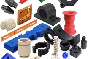
CNC machining is a blend of art and science, and mastering spindle rotation control can significantly enhance the quality and efficiency of machining parts. Whether you’re working with a CNC mill, lathe, or machining center, understanding the nuances of spindle rotation direction is crucial. Let’s dive into the world of CNC machining parts and uncover the secrets of spindle rotation control.
Understanding Spindle Rotation
Spindle rotation is essential in CNC machining. It’s all about the direction—clockwise (CW) or counterclockwise (CCW)—and getting this right is vital for the machining process. The direction depends on the tool type and the setup.
To describe spindle rotation direction accurately, you need a definite standard and reference point. Typically, this is the viewpoint from the spindle head area, looking along the spindle centerline towards its end face. For CNC mills, machining centers, and lathes, the viewpoint is similar: from the operator’s position, facing the front of the machine.
Milling Direction
In CNC milling, you usually look down the spindle centerline perpendicular to the workpiece surface. However, a more practical approach is viewing from the operator’s position facing the machine’s front. This standard view allows you to use terms like CW and CCW accurately.
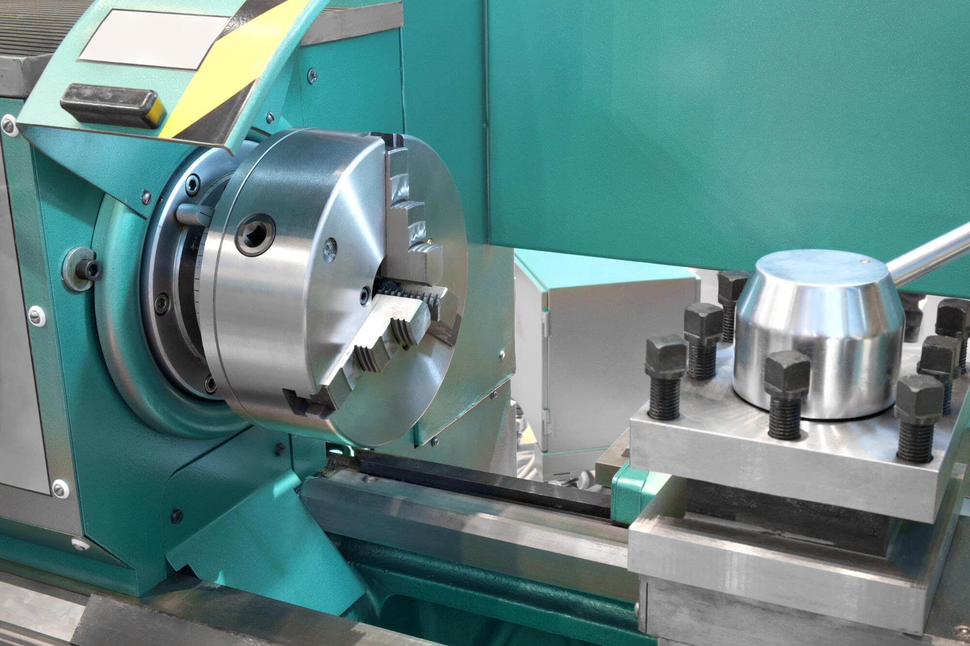
Turning Direction
For CNC lathes, the concept is the same. Operators face the machine front, and the viewpoint from the spindle head area looking towards the tailstock area determines the correct rotation direction. Here’s a simple diagram to illustrate:
Front View of CNC Lathe:

      Tailstock
        |
        |          CW (M03)
        v        [----->]
[----->]   Spindle Head

   CCW (M04)
In this view, CW rotation (M03) is to the right, and CCW rotation (M04) is to the left, as seen from the spindle head.
Practical Application
To make it more concrete, here are some programming examples demonstrating different methods to set spindle speed and direction:
Example A: Milling Application
This example combines spindle speed and rotation direction with the approach to the workpiece:
N1 G20
N2 G17 G40 G80
N3 G90 G00 G54 X14.0 Y9.5
N4 G43 Z1.0 H01 S600 M03
In this format, the spindle speed (S600) and direction (M03) are set together with the movement commands.
Example B: Separate Commands
Although technically correct, separating speed and direction commands can be less efficient:
N1 G20
N2 G17 G40 G80
N3 G90 G00 G54 X14.0 Y9.5 S600
N4 G43 Z1.0 H01 M03
This separation makes the program harder to read and manage.
Example C: Non-Sequential Approach
Again, technically correct but not practical:
N1 G20
N2 G17 G40 G80
N3 G00 G90 G54 X14.0 Y9.5 M03
N4 G43 Z1.0 H01
N5 G01 Z-0.1 F50.0 S600
Starting rotation (M03) without an immediate speed command can lead to issues if not managed correctly.
Spindle Control in Lathes
For lathes, the same principles apply, but the setup might differ slightly. Here’s another example:
Example D: Turning with G50
Using the old G50 method to set speed:
N1 G20
N2 G50 X13.625 Z4.0 T0100
N3 G96 S420 M03
G96 sets the constant surface speed (CSS), and the system calculates the actual RPM based on this value and the current workpiece diameter.
Example E: Modern Approach
A more modern method without G50:
N1 G20
N2 G96 S420 M03
N3 G00 X6.0 Z0.1
N4 G01 Z-0.4 F0.04 T0101
This approach calculates spindle speed based on the tool offset values and stores them in the system’s workpiece geometry offset register.
Data Table: Common Commands
Here’s a quick reference table for spindle rotation commands:
| Command | Function | Example |
|---|---|---|
| S | Spindle Speed Address | S600 |
| M03 | Spindle Rotate Clockwise (CW) | M03 |
| M04 | Spindle Rotate Counterclockwise (CCW) | M04 |
Key Takeaways
Understanding spindle rotation control and programming can drastically improve the efficiency and quality of CNC machining parts. By mastering these commands and their applications, you ensure that your CNC machine operates smoothly, producing high-quality parts with precision.
Other Articles You Might Enjoy
- CNC Machining Parts: The Art of Spindle Speed and Direction Control
CNC machining is a fascinating world where precision meets creativity. At the heart of this intricate dance is the spindle, a critical component that dictates the success of machining parts.…
- Requirements for CNC Machining Parts
Preparation Work Complete the necessary preparation before machining, including process analysis, process route design, tool and fixture selection, and program compilation. online cnc machining service Operating Steps and Contents Start…
- What are the requirements for CNC machining of bearing parts?
Bearings are common and important parts in the automotive industry, which can support transmission components and transmit torque. Generally, CNC machining centers are used to process bearing parts. So what…
- Evolution of Mills and Machining Centers: The Future of CNC Machining Parts
Stepping into the world of CNC machining, you quickly realize how pivotal mills and machining centers are in crafting precise parts. Over time, these machines have evolved significantly, transforming from…
- Precision CNC Machining of Steel: High-Volume Production
Precision CNC Machining and High-Volume Production As an integral part of modern manufacturing processes, Precision Computer Numerical Control (CNC) machining brings about unmatched accuracy and consistency in the production of…
- Aluminum CNC Machining Service for Custom Parts
Aluminum CNC machining stands at the forefront of modern manufacturing, epitomizing precision, versatility, and efficiency. With its widespread applications across industries ranging from aerospace to automotive and beyond, aluminum CNC…