Common Casting Structures
Taper
To facilitate the removal of the cast from the mold and reduce resistance, a certain degree of taper is added in the design along the molding direction. This taper helps the cast to be easily removed from the mold without getting stuck or damaged. Typically, the taper is set around 3 degrees, approximately 1:20 in ratio. For small parts, this taper can be omitted from the drawing, but for large parts, it must be clearly marked.
Fillet
To prevent damage to the sand mold during casting and avoid shrinkage cavities and cracks during cooling, the edges of the cast are designed as fillets. This design prevents sharp corners that can lead to cracks, thus improving the strength and longevity of the cast.
Wall Thickness Equality
The design should aim for uniform wall thickness to avoid defects such as shrinkage cavities and cracks caused by uneven cooling rates. Gradual changes in wall thickness are crucial to prevent sudden changes that can lead to stress concentration and cracks.
Least Wall Thickness
The wall thickness of the cast should not be too thin to ensure the mold cavity is fully filled, thus preventing defective products. Therefore, the minimum wall thickness must be specified in the design to ensure the integrity and quality of the cast.
Common Machining Structures
Cylindrical Projection or Recessed Surface
To ensure stable contact between the machined parts, reduce the machined surface, and lower costs, projections and recesses are often added to the design. These structures not only reduce machining time and difficulty but also enhance the stability of the parts.
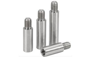
Chamfer or Radius
To avoid stress concentration and facilitate installation and safety, small chamfers or radii are added at the ends of rods or at the transitions of shafts. This design prevents sharp edges from causing injury and avoids breakage due to stress concentration.
Undercut
To facilitate tool withdrawal and avoid incomplete machining surfaces, undercuts are designed at shafts or holes. This sudden change in diameter significantly improves machining efficiency and reduces the defect rate.
Drill Hole
For easy positioning and to prevent drill bit damage, the surface to be drilled must be perpendicular or greater than 60 degrees to the axis of the hole. Common drill hole structures include blind holes, tapered holes, countersunk holes, and spot faces.
Common Sheet Pressing Structures
Radius
To avoid stress concentration at sharp corners and prevent fractures, the external and internal corners of the sheet pressing parts are designed as small radii. This design significantly improves the strength and longevity of the sheet pressing parts.
Least Bend Radius
To prevent the sheet material from breaking during bending, the minimum bend radius must be restricted. A small bend radius can lead to cracks or fractures during the bending process, affecting product quality.
Enchasing Structures
Enchasing Design
To ensure a secure connection and improve the adhesion of the bonding surfaces, projections and grooves are designed on the surface of the enchasing parts. To avoid stress concentration at the sharp corners of the enchasing parts, fillets are added at the ends and grooves. This design improves the strength and durability of the enchasing parts.
Example Data Table
To better understand the technological craftsmanship of part structures, the following data table compares the effects of different designs:
| Item | Design Requirements | Advantages | Disadvantages |
|---|---|---|---|
| Taper | 3 degrees | Facilitates mold removal, reduces resistance | May increase design complexity |
| Fillet | R3~5 | Prevents sand mold damage, reduces shrinkage and cracks | Increases machining time and cost |
| Wall Thickness Equality | Uniform wall thickness | Avoids defects due to uneven cooling | Increases design difficulty |
| Least Wall Thickness | Specified minimum thickness | Ensures mold cavity is fully filled, reduces defects | Requires precise calculation and control |
| Projection and Recess | Uneven height | Enhances part stability, reduces machining time and cost | Uneven height increases machining difficulty and time |
| Chamfer and Radius | Small chamfer or radius | Avoids stress concentration, facilitates installation and safety | Increases design and machining complexity |
| Undercut | Groove design | Improves machining efficiency, reduces defects | Requires precise tools and techniques |
| Drill Hole | Perpendicular or >60 degrees | Prevents drill bit damage, ensures hole accuracy | Requires precise positioning and operation |
| Radius | Sharp corners to small radii | Prevents fractures, improves strength | Increases design and machining time |
| Bend Radius | Restricted minimum radius | Prevents cracks or fractures during bending | Requires strict control of bend radius |
| Enchasing Design | Projections and grooves | Improves strength and durability of enchasing parts | Increases design and machining complexity |
Through the above table, it is easier to understand how different designs impact the technological craftsmanship of part structures, helping us make better decisions during the design and machining process. The craftsmanship of part structures not only affects the quality and performance of the product but also directly relates to production costs and efficiency. Therefore, during the design and machining process, we need to consider various factors comprehensively to ensure the optimal craftsmanship of the parts.
Other Articles You Might Enjoy
- Innovative CNC Machining for Custom Medical Instruments
Innovative CNC Machining for Custom Medical Instruments Computer Numeric Control (CNC) machining is an innovative automated process that utilizes computer software to control machine tools. The use of CNC machines…
- Unveiling the Effectiveness of Bead Blasting in CNC Machining(what is cnc Norton)
Bead blasting is a critical procedure inside an overarching process known as Computer Numerical Control (CNC) machining. Known for its precise and accurate nature, bead blasting helps remove surface deposits…
- Masterful Precision: Elevating Aluminum Craftsmanship with Laser Cutting
Laser cutting penetrates and slices through materials with a high-powered laser beam guided by CNC (Computer Numerical Control). The process achieves high-precision cuts, intricate detail work, and polished edges on…
- design for 3d printing how to reduce your cost
Relevance and Benefits of Cost Reduction in 3D Printing In an era where innovation is pivotal, 3D printing emerges as a transformative force across numerous industries, from manufacturing complex aerospace…
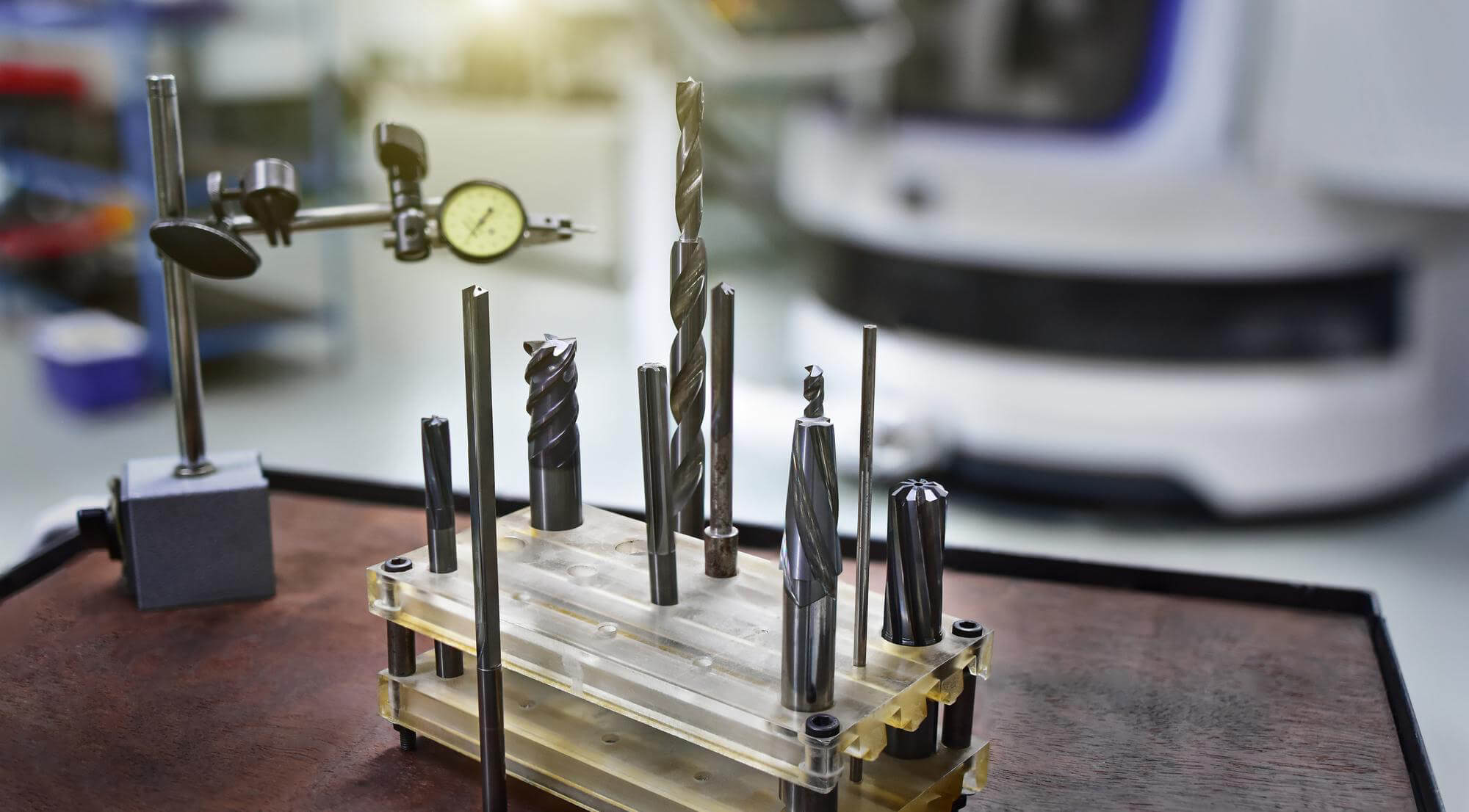
- Comprehensive Guide to Metal Cutting Tools
In modern mechanical manufacturing, metal cutting processes are the most widely used methods, accounting for over 50% of the total workload in mechanical manufacturing. Whether it's a conventional lathe, an…
- Enhancing Optical Components with CNC Machining: Glass vs. Polycarbonate
Introduction to CNC Machining CNC (Computer Numerical Control) machining stands as a pivotal technology in the manufacturing of optical components, enabling the precise shaping of materials with minimal human intervention.…