What is CNC Milling? How Does it Differ from Traditional Milling?
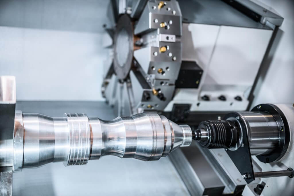
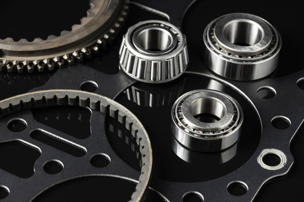
Milling is one of the most versatile machining processes used to manufacture parts with complex internal and external geometries. It involves rotating cutting tools to remove material from a workpiece, making it a widely adopted method for producing parts like splines, gears, and components with intricate structures.
The evolution of technology has led to the development of Computer Numerical Control (CNC) milling, a more precise and automated version of traditional milling. CNC milling has transformed manufacturing by offering higher accuracy, efficiency, and consistency.
What is CNC Milling?
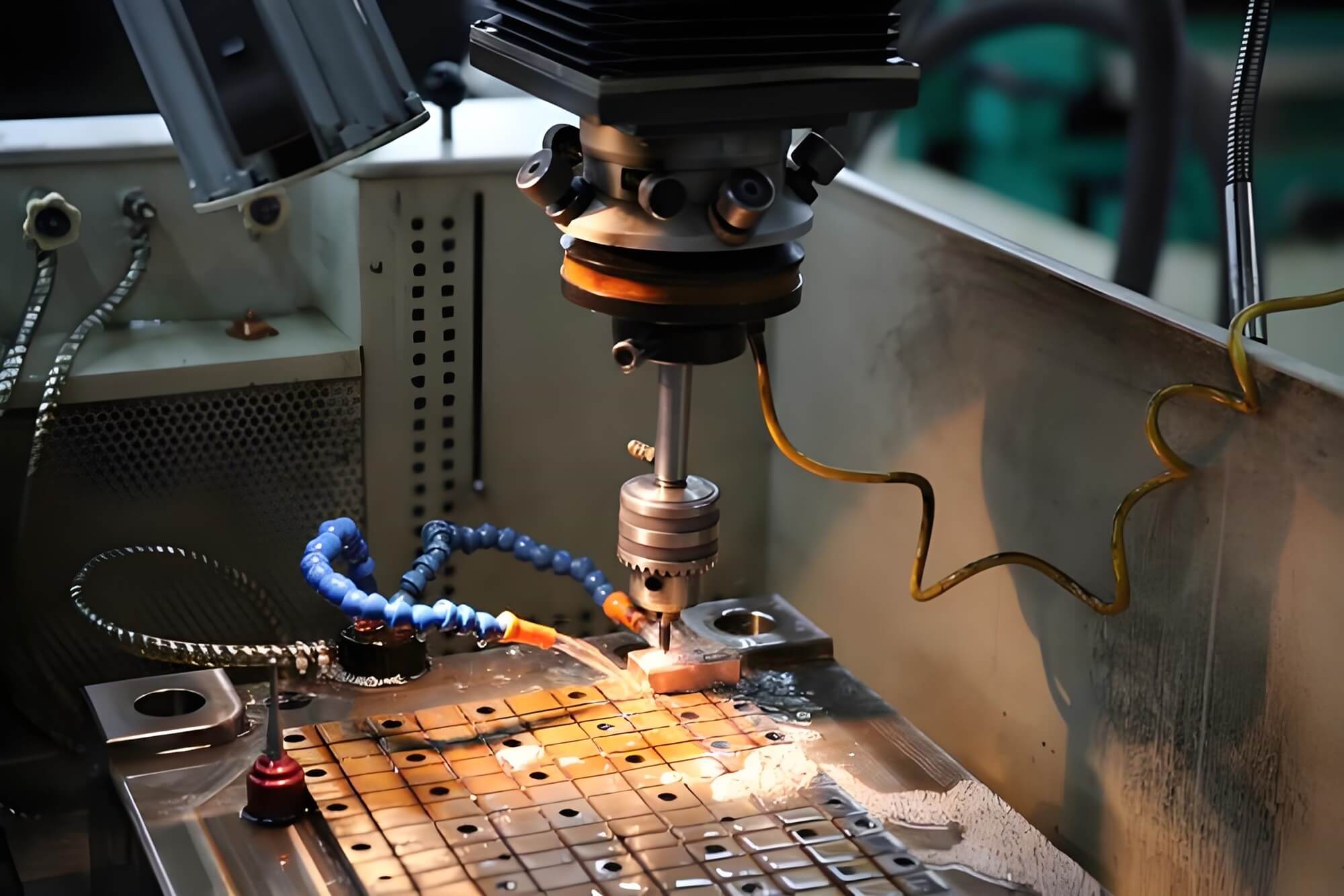
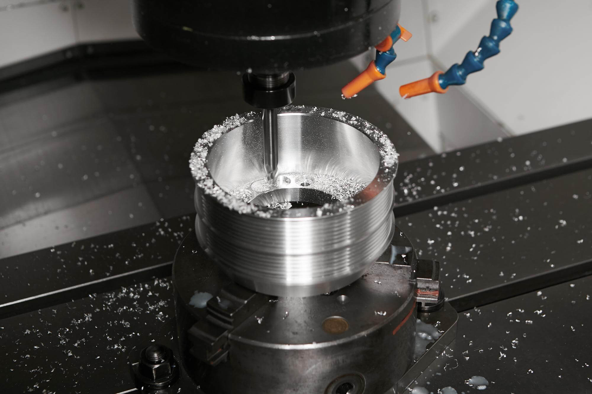
CNC (Computer Numerical Control) milling is a precision machining process that uses computer technology to control the movement of rotary cutting tools, progressively removing material from a stationary workpiece. This process is based on pre-programmed instructions derived from CAD (Computer-Aided Design) models. The automation and precision in CNC milling make it ideal for complex and high-precision parts.
CNC milling is used in various industries, including aerospace, automotive, medical devices, and electronics. It works with a wide range of materials, such as metals (steel, aluminum, titanium), plastics, and even wood.
Key Components of a CNC Milling System
Several key components define the CNC milling process:
- Control Unit: Reads and interprets G-code instructions, controlling tool and workpiece movement.
- Cutting Tool: Rotary cutters remove material, moving along multiple axes for complex cuts.
- Workholding Device: Holds the workpiece in place to prevent movement during milling.
- Spindle: Holds the cutting tool and rotates at high speeds to perform the cutting.
- Axes of Motion: Operates on multiple axes (3, 4, or 5 axes), allowing for multi-dimensional cutting.
The CNC Milling Process
The CNC milling process involves several stages to achieve high-precision results:
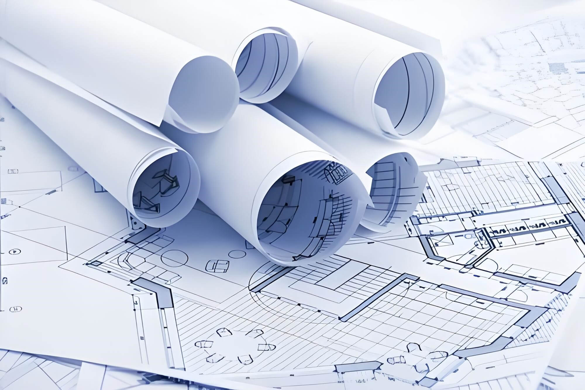
- CAD Model Creation: Create a 2D or 3D CAD model using software like Autodesk Inventor, SolidWorks, or Fusion 360 to define specifications and tolerances.
- CAM Programming and G-Code Generation: Import the CAD model into CAM software to convert it into G-code, which provides instructions for tool paths, cutting speeds, and feed rates.
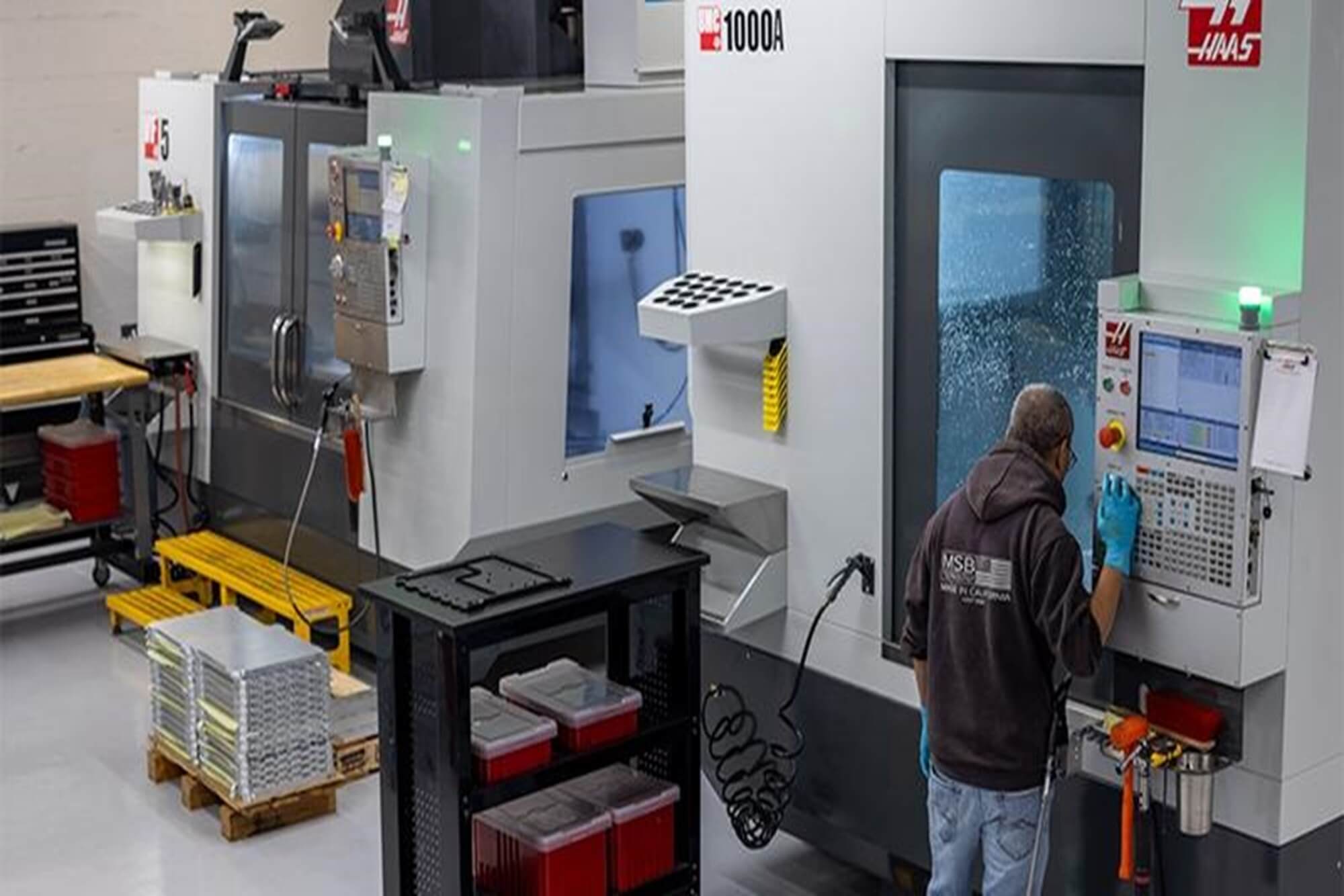
- Machine Setup: Install the correct tool, secure the workpiece, and calibrate the CNC machine. Load the G-code program into the control unit.
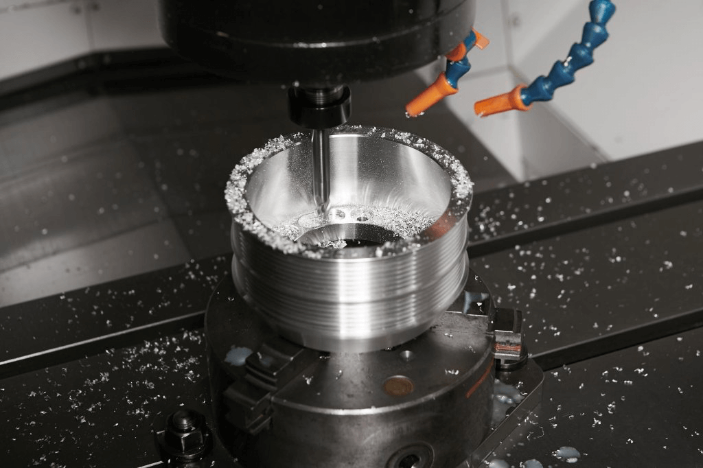
- Milling Operation: The tool follows pre-programmed paths to remove material and shape the workpiece. The machine automates movements to maintain precision.
- Post-Processing and Inspection: Inspect the part for tolerances and surface finishes. Perform additional post-processing steps, like deburring, if necessary.
Types of CNC Milling Operations
Different types of CNC milling operations are used to create specific features:
- End Milling: Cutting with the tool’s end to create slots, holes, or complex shapes.
- Face Milling: Producing flat surfaces by cutting with the tool’s face.
- Angular Milling: Creating angled surfaces or tapers.
- Form Milling: Producing complex profiles like gears and splines.
- Thread Milling: Creating internal or external threads.
- Helical Milling: Producing spiral or helical features, such as gears.
Traditional Milling vs. CNC Milling
- Manual Operation vs. Computer Control:
Traditional milling relies on manual control, where the machinist adjusts feed rates, spindle speeds, and tool positioning in real-time. In contrast, CNC milling is fully automated, following pre-programmed G-code instructions, reducing human error and increasing consistency. - Precision and Accuracy:
CNC milling achieves much higher precision, with tolerances within microns, making it suitable for industries where tight tolerances are critical. Traditional milling depends on the operator’s skill, which can lead to small variations between parts. - Complexity and Flexibility:
CNC milling is ideal for complex parts with intricate geometries. CNC machines, especially 5-axis models, can cut complex shapes in a single setup. Traditional milling is typically used for simpler parts or prototypes. - Scalability and Efficiency:
CNC milling is more efficient for larger production runs due to its automation and repeatability. Traditional milling may be more cost-effective for small runs or custom parts due to lower initial setup costs. - Automation and Labor:
CNC milling requires less operator intervention, reducing labor costs and increasing productivity. Manual milling needs a skilled operator throughout the process. - Tool Changes and Versatility:
CNC milling machines can automatically change tools mid-operation, reducing downtime and increasing versatility, while traditional milling requires manual tool changes.
Advantages of CNC Milling Over Traditional Milling
- Higher Precision: Achieves tighter tolerances and more complex geometries.
- Repeatability: Produces identical parts across production runs.
- Efficiency: Performs multiple operations in a single setup.
- Automation: Requires less operator intervention, lowering labor costs.
- Complex Part Production: Machines complex parts with fewer setups.
How Does CNC Milling Work?
The core of CNC milling’s capability lies in its automation—each step of the milling process, from design to execution, is guided by detailed digital instructions derived from CAD (Computer-Aided Design) and CAM (Computer-Aided Manufacturing) software. Unlike manual milling, CNC milling eliminates the need for human intervention in tool movement, ensuring consistency and reducing errors. This automation also provides flexibility for both small and large production runs, with each part being identical in quality and precision.
The CNC Milling Process in Detail
The CNC milling process can be divided into several stages, each essential for successful machining. From the initial design phase to post-processing, CNC milling ensures that even the most complex parts are manufactured with precision and consistency.
1. Design Phase (CAD Model Creation)
The first step in CNC milling is creating a CAD model. Using software like AutoCAD, SolidWorks, or Fusion 360, engineers design a 2D or 3D representation of the part, defining its exact specifications, including dimensions and tolerances. This model serves as a digital blueprint for the entire milling process.
- 2D CAD Models: Used for simpler parts with flat features.
- 3D CAD Models: Utilized for complex parts with intricate geometries.
The CAD model’s precision ensures that the final product meets all necessary specifications.
2. Programming the CNC Machine (CAM and G-Code)
Once the CAD model is complete, CAM software converts it into G-code, a machine-readable language that instructs the CNC machine on how to perform the cutting operations. Key parameters include:
- Tool paths: The cutting tool’s path.
- Cutting speeds and feeds: The tool’s movement and rotation speed.
- Cut depth: The depth of each cut.
- Tool changes: Instructions for automatic tool changes when needed.
The G-code ensures the machine performs precise movements, minimizing the chance of errors.
3. Workpiece Setup and Alignment
The workpiece must be securely mounted to the machine table using clamps or custom fixtures. It is then aligned with the machine’s coordinate system. “Zeroing” is the process of setting the machine’s coordinates to match the CAD model, ensuring accurate tool movements.
Proper alignment is essential for multi-axis CNC milling operations, where precise movements across multiple planes are required.
4. Milling Operations: Cutting and Shaping the Workpiece
With the workpiece in place and the program loaded, the CNC machine begins the milling process. The cutting tools remove material according to the programmed tool paths. Types of milling operations include:
- Face Milling: Removes material from the top surface to create a flat finish.
- End Milling: Used to cut features like pockets and grooves with the side of the tool.
- Profile Milling: Follows the outer contour of the part to create specific shapes.
- Slot Milling: Cuts narrow grooves or slots.
- Drilling and Boring: Creates or refines holes.
- Thread Milling: Cuts internal or external threads.
- Contour Milling and 3D Surface Milling: Follows curved surfaces or creates freeform shapes.
Each operation is chosen based on the part’s design and desired features.
5. Post-Processing and Quality Control
Once the milling operations are complete, the part may require additional post-processing steps, such as:
- Deburring: Removing sharp edges or residual material.
- Surface finishing: Polishing or sanding the surface.
- Coating: Applying protective or decorative finishes.
- Dimensional inspection: Using precision tools to ensure the part meets specifications.
Post-processing ensures the part is free of defects and ready for use. CNC milling’s precision allows for tight tolerances, but careful inspection verifies that all requirements are met.
What Are the Different Types of CNC Milling?
To meet the diverse requirements of various industries, different types of CNC milling operations have been developed. These operations vary based on the orientation of the spindle, the complexity of the part, and the type of cut being performed. Each type of CNC milling machine and process is designed for specific tasks, ensuring precision and efficiency in manufacturing.
In this section, we will explore the different types of CNC milling and how they are applied in various industries, including vertical, horizontal, and multi-axis milling, along with various cutting techniques like face milling, end milling, and more.
Classification of CNC Milling Types
CNC milling can be classified based on several factors, including the orientation of the cutting tool, the number of axes used in the operation, and the specific type of cutting process. Each type offers unique advantages depending on the nature of the part being produced.
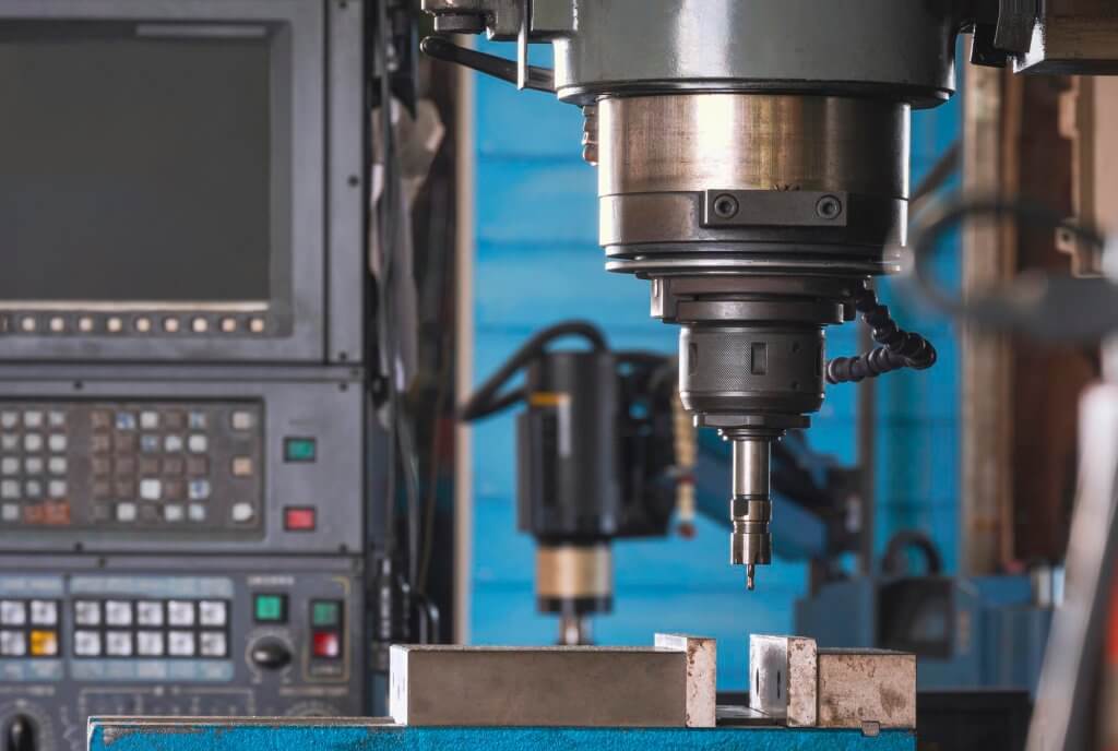
1. Vertical CNC Milling
In vertical CNC milling, the spindle is vertically oriented, allowing the cutting tool to move up and down along the Z-axis. Vertical milling machines are widely used due to their versatility and simplicity. They are best suited for tasks such as drilling, slotting, and machining flat surfaces.
- Advantages:
- Ideal for small-to-medium batch production.
- Easier setup and operation compared to horizontal machines.
- Cost-effective for less complex jobs.
- Common Applications:
- Machining flat surfaces, drilling holes, and making slots.
- Manufacturing components like brackets, plates, and housings.
| Feature | Description |
|---|---|
| Axis Configuration | 3-axis (X, Y, Z) |
| Typical Materials | Aluminum, steel, plastic |
| Common Operations | Face milling, drilling, slotting, pocket milling |
| Complexity Level | Suitable for low-to-medium complexity parts |
2. Horizontal CNC Milling
In horizontal CNC milling, the spindle is mounted horizontally, making it suitable for parts requiring deep cuts or more material removal in a single pass. Horizontal milling machines are ideal for larger, heavier parts and bulk material removal.
- Advantages:
- Suitable for heavier workpieces and deep cutting.
- More efficient chip removal due to gravity aiding the process.
- Common Applications:
- Large parts used in industries such as automotive and heavy equipment manufacturing.
- Machining deep slots and large surface areas.
| Feature | Description |
|---|---|
| Axis Configuration | 3-axis or 4-axis (X, Y, Z + rotating table) |
| Typical Materials | Steel, titanium, iron |
| Common Operations | Side milling, gear cutting, deep cavity milling |
| Complexity Level | Suitable for large and complex parts |
3. 5-Axis CNC Milling
5-axis CNC milling machines are among the most advanced, allowing movement along five axes (X, Y, Z, and two rotary axes). This flexibility allows for machining complex geometries without repositioning the workpiece.
- Advantages:
- Ideal for highly complex parts with intricate geometries.
- Reduces setup time by machining multiple surfaces in a single operation.
- Increases precision and minimizes human error.
- Common Applications:
- Aerospace and automotive components, medical implants, turbine blades, and complex molds.
4. 4-Axis CNC Milling
4-axis CNC milling introduces a rotary motion along the X-axis, called the A-axis. This extra axis allows for more complex shapes and continuous cutting around cylindrical parts.
- Advantages:
- Enables machining of cylindrical shapes and angled features.
- Reduces the need for repositioning, improving accuracy.
- Common Applications:
- Engraving, gear cutting, and machining cylindrical parts like pipes or shafts.
5. 3+2 Axis CNC Milling (Positional 5-Axis)
3+2 axis CNC milling is a type of 5-axis machining where the two additional axes are used to position the part at a fixed angle rather than moving continuously during machining.
- Advantages:
- Cost-effective and easier to program than full 5-axis milling.
- Useful for machining parts with angled features.
- Common Applications:
- Die and mold machining, aerospace parts, and medical devices.
Types of Milling Operations
CNC milling machines can also be classified based on the type of cutting operation performed. The chosen operation depends on the geometry of the part and the desired surface finish. Many operations are combined to create complex parts.
1. Face Milling
Face milling is used to produce flat surfaces. The cutting tool is positioned perpendicular to the workpiece, using the cutting edges on the tool’s face to remove material. This method is efficient for large, flat areas and provides a fine surface finish.
- Advantages:
- Creates smooth, flat surfaces.
- Removes large amounts of material in a single pass.
- Common Applications:
- Flat surfaces on metal or plastic parts.
2. End Milling
End milling uses a cutting tool with teeth on the end and sides to remove material, allowing for the creation of slots, cavities, and profiles. This versatile method is used for both roughing and finishing operations.
- Advantages:
- Suitable for creating complex features, such as pockets and contours.
- Common Applications:
- Cutting internal cavities and engraving.
3. Chamfer Milling
Chamfer milling creates angled cuts along the edges of a part to form a beveled surface. It is used for deburring sharp edges and preparing parts for assembly.
- Advantages:
- Provides clean, safer edges on parts.
- Common Applications:
- Preparing parts for welding or bolting.
4. Slot Milling
Slot milling involves cutting narrow slots or grooves into the workpiece. It is used for creating keyways or guide rails in mechanical components.
- Advantages:
- Ideal for creating linear channels with high accuracy.
- Common Applications:
- Keyways, guide rails, and other mechanical features requiring slots.
5. Profile Milling
Profile milling cuts along the outer contour of a part to create a specific shape. The cutting tool follows the defined profile, removing material as it goes.
- Advantages:
- Ideal for machining complex external shapes.
- Common Applications:
- Mold and die making, manufacturing of housings with complex outlines.
6. T-slot Milling
T-slot milling creates a T-shaped slot in a workpiece, commonly used for securing clamps and fixtures in machine tables.
- Advantages:
- Creates strong interlocking joints.
- Common Applications:
- Clamping fixtures and tool holders.
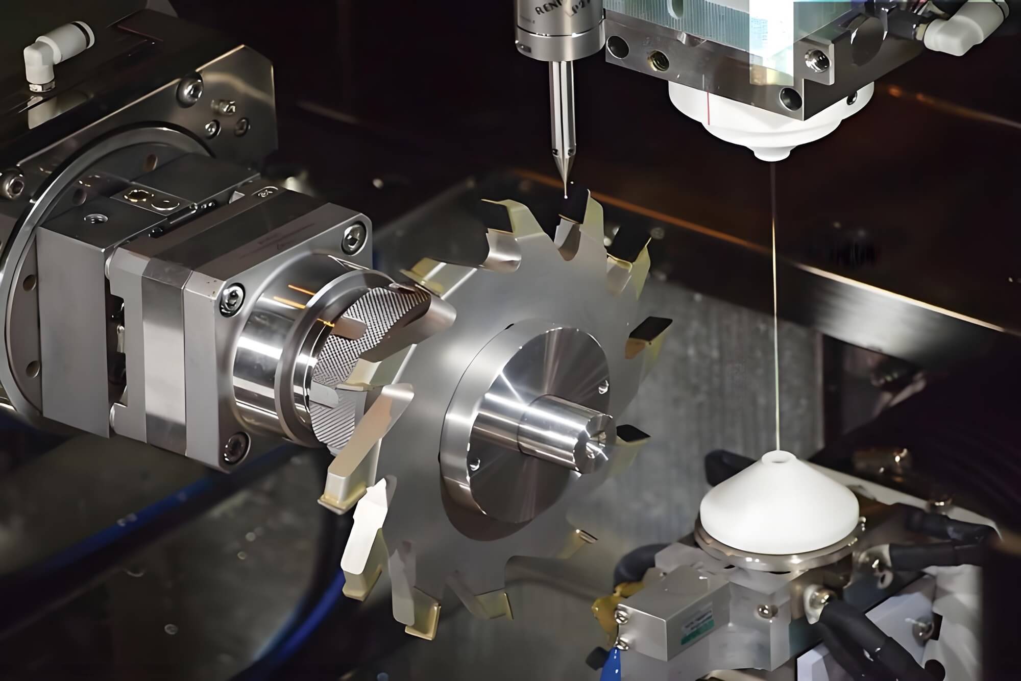
7. Form Milling
Form milling uses specially shaped cutting tools to create complex profiles like gears and splines. These tools are custom-made for the desired geometry.
- Advantages:
- Produces complex shapes in a single pass.
- Common Applications:
- Gear cutting and creating intricate surface profiles.
8. Thread Milling
Thread milling is a technique for cutting internal or external threads. Unlike tapping, thread milling uses a multi-point cutting tool, allowing for greater flexibility and precision in thread formation.
- Advantages:
- Provides precise thread cutting with less tool wear.
- Common Applications:
- Threading fasteners, aerospace, and automotive components.
Comparison of Different CNC Milling Types and Operations
| Milling Type | Axis Configuration | Common Operations | Materials | Best For |
|---|---|---|---|---|
| Vertical CNC Milling | 3-axis (X, Y, Z) | Face milling, drilling | Aluminum, steel, plastic | Flat surfaces, simple geometries |
| Horizontal CNC Milling | 3 or 4-axis | Side milling, deep cuts | Steel, titanium, iron | Deep cuts, large parts |
| 5-Axis CNC Milling | 5-axis | Complex 3D surfaces | Aluminum, titanium | Aerospace, medical implants |
| 4-Axis CNC Milling | 4-axis | Engraving, cylindrical cuts | Metal, plastic | Cylindrical parts, angled cuts |
| 3+2 Axis CNC Milling | 5-axis (positional) | Die and mold making | Aluminum, steel | Complex geometries with angled surfaces |
CNC milling offers a wide range of capabilities to meet the specific needs of different industries. Each type of machine and operation provides unique benefits, allowing manufacturers to choose the best method for their production needs, from high-volume runs to highly complex custom parts.
What Are the Main Components of a CNC Milling Machine?
The performance and versatility of a CNC milling machine rely on the design and configuration of its main components. Each plays a critical role in the machining process, contributing to the overall precision, efficiency, and functionality. Below are the key components of a CNC milling machine and their functions:
1. Machine Frame and Base
- Machine Frame: Acts as the backbone, providing structural support and alignment for all other components. It ensures stability and reduces vibration, which is vital for precision.
- Base: The bottom structure supports the machine’s weight and houses systems like coolant, hydraulic, and chip management, also absorbing vibrations for better accuracy.
Both the frame and base provide the necessary stability for heavy-duty operations, ensuring long-term operational efficiency.
2. Spindle and Spindle Motor
- Spindle: Holds the cutting tool and rotates it during machining, performing operations like cutting, drilling, and shaping. It can be mounted vertically or horizontally.
- Spindle Motor: Powers the spindle, controlling its speed and torque, which are crucial for determining cutting power and precision. Variable-speed motors are often used to adjust for different materials.
The spindle and motor together provide the cutting force needed for machining, with precision in speed and torque control being essential for smooth, accurate cuts.
3. CNC Control Unit
- G-Code Interpreter: Translates the digital instructions (G-code) into machine movements, controlling spindle rotation, axis motion, and tool changes.
- Human-Machine Interface (HMI): Allows operators to monitor and control the machine through a graphical interface, displaying real-time feedback and enabling manual inputs.
- Feedback and Sensors: Track the cutting tool’s position and make adjustments to maintain precision.
The control unit is the “brain” of the machine, ensuring all operations are carried out precisely according to the programmed instructions.
4. Linear Motion Guideways and Ball Screws
- Linear Motion Guideways: Provide smooth, controlled motion along the X, Y, and Z axes, minimizing friction and allowing for precise tool movement.
- Ball Screws: Convert rotational motion from motors into linear movement, ensuring accurate positioning of the cutting tool.
These components are crucial for high precision and repeatability, guiding the cutting tool accurately along the programmed path.
5. Machine Table and Workholding Devices
- Machine Table: Provides a stable platform for mounting the workpiece. It can move along one or more axes, positioning the workpiece relative to the cutting tool.
- Workholding Devices: Secure the workpiece during machining using vices, clamps, or custom fixtures to prevent movement.
A stable and well-secured workpiece ensures accurate machining, free from unwanted vibrations or shifts during cutting.
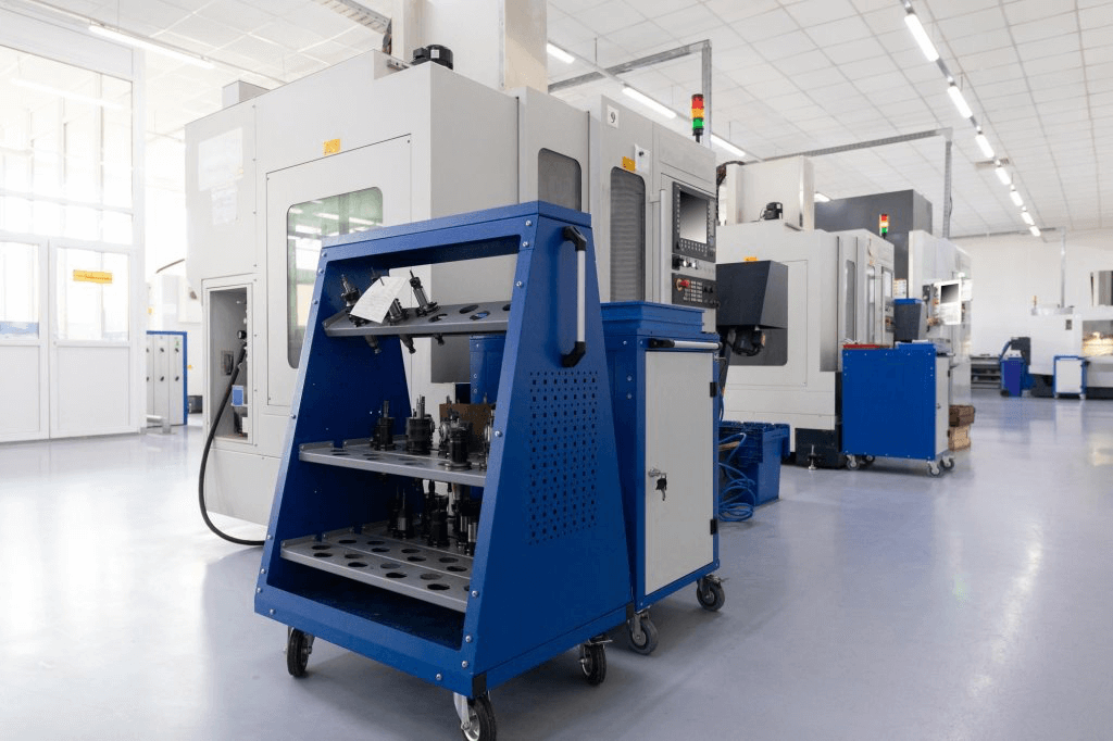
6. Tool Changer and Tool Holders
- Tool Changer: An automated system that stores multiple cutting tools and switches them as needed during operations, reducing downtime.
- Tool Holders: Securely attach the cutting tools to the spindle, ensuring a firm grip and easy tool changes.
The tool changer and holders improve machine versatility, allowing it to perform various operations with minimal interruptions.
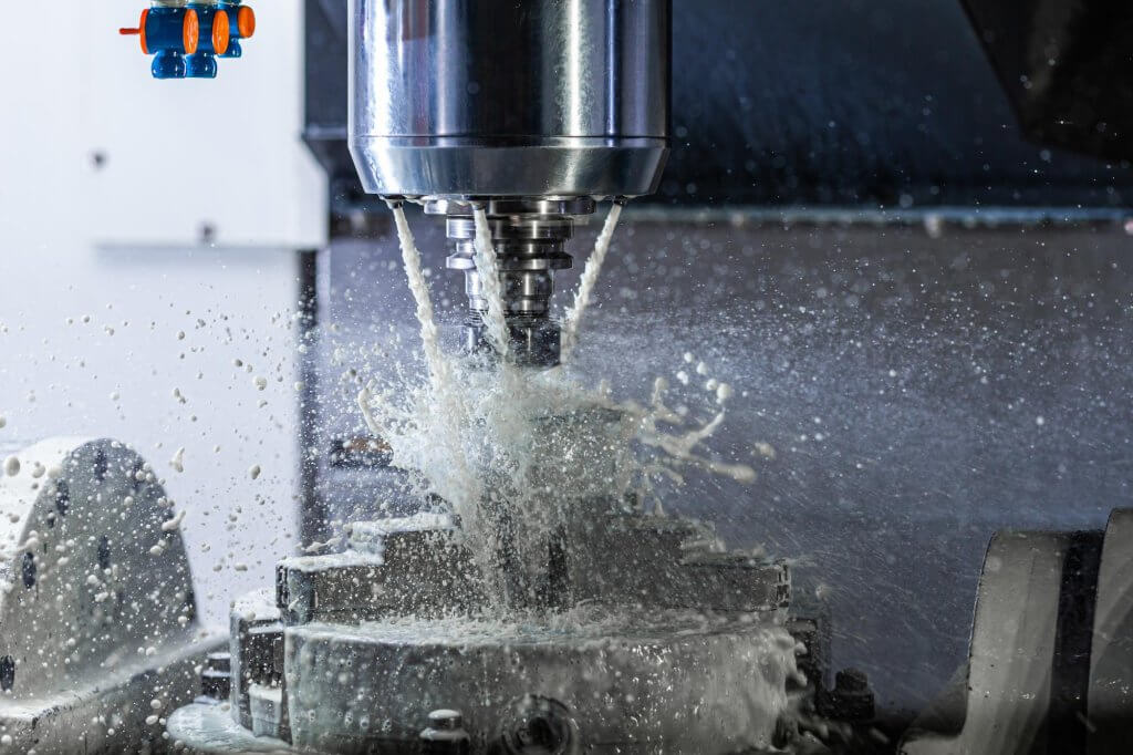
7. Coolant System
- Coolant: Helps to dissipate heat, lubricate the cutting tool, and remove chips. It prevents overheating, which could damage the tool or workpiece.
- Coolant Pump and Reservoir: Circulates coolant to the cutting area, ensuring continuous cooling during machining.
A proper coolant system extends tool life and ensures better surface finish by preventing thermal distortion.
8. Chip Management System
- Chip Conveyor: Automatically removes chips from the machine, keeping the work area clean and preventing interference with the machining process.
- Chip Guards: Prevent chips from scattering and help maintain a safe, clean workspace.
Effective chip management ensures smoother operations and reduces downtime from chip buildup.
9. Servo Motors and Drives
- Servo Motors: Control the movement, speed, and torque of the machine’s axes, ensuring precise and controlled motion.
- Drives: Manage the power supplied to the servo motors, allowing them to respond accurately to the control unit’s commands.
Servo motors and drives are essential for maintaining high precision in cutting tool movements, enabling the machine to follow the programmed paths with minimal deviation.
What Types of Materials Can Be Processed by CNC Milling?
CNC (Computer Numerical Control) milling is one of the most versatile and widely used machining processes in modern manufacturing. It is capable of shaping and cutting a wide variety of materials with precision and efficiency. The adaptability of CNC milling comes from its ability to handle different types of materials, ranging from metals and plastics to composites and wood. Each material poses unique challenges and benefits in terms of machinability, strength, durability, and finishing requirements.
In this section, we will explore the most common materials used in CNC milling, their characteristics, and the industries where they are applied. Additionally, we will provide insights into how different materials react to the milling process and why certain materials are more suitable for specific applications. The following sections are organized by material type, covering metals, plastics, composites, and other materials like ceramics and wood.
1. Metals
Metals are some of the most commonly used materials in CNC milling due to their strength, durability, and machinability. Different types of metals have specific properties that make them suitable for various industrial applications. Below are the most common metals used in CNC milling:
1.1 Aluminum
Aluminum is one of the most popular materials in CNC milling because of its excellent machinability, light weight, and good corrosion resistance. It is easy to machine, which results in faster production times and lower tool wear. Additionally, aluminum is highly versatile and is available in various alloys that offer different levels of strength and hardness.
- Characteristics: Lightweight, high strength-to-weight ratio, good corrosion resistance, excellent machinability.
- Common Applications: Aerospace components, automotive parts, consumer electronics, and medical devices.
| Property | Description |
|---|---|
| Density | Lightweight, ~2.7 g/cm³ |
| Corrosion Resistance | High, especially with protective coatings |
| Machinability | Excellent, can be milled at high speeds |
| Typical Alloys | 6061, 7075, 2024 |
| Common Applications | Aircraft parts, automotive components, electronics |
1.2 Steel
Steel, particularly stainless steel and carbon steel, is widely used in CNC milling for its strength, hardness, and durability. While it is more challenging to machine compared to softer metals like aluminum, steel’s strength and resistance to wear make it a preferred choice for heavy-duty applications.
- Characteristics: Strong, durable, resistant to wear, available in a wide range of grades.
- Common Applications: Automotive components, structural parts, tools, and machine components.
| Property | Description |
|---|---|
| Density | High, ~7.85 g/cm³ |
| Corrosion Resistance | Stainless steel has high corrosion resistance |
| Machinability | Moderate to difficult, depending on the grade |
| Typical Grades | 304, 316 (stainless), A36, 1045 (carbon) |
| Common Applications | Structural parts, machine tools, automotive parts |
1.3 Brass
Brass is an alloy of copper and zinc, and it is known for its ease of machining, low friction properties, and good corrosion resistance. Brass is often chosen for parts that require a high level of precision and intricate detailing, such as valves, fittings, and electrical components.
- Characteristics: Excellent machinability, good corrosion resistance, high conductivity.
- Common Applications: Electrical components, plumbing fittings, musical instruments.
| Property | Description |
|---|---|
| Density | Medium, ~8.5 g/cm³ |
| Corrosion Resistance | Good, especially in marine environments |
| Machinability | Excellent, very easy to machine |
| Common Alloys | C36000, C38500 |
| Common Applications | Electrical connectors, plumbing, precision components |
1.4 Titanium
Titanium is a lightweight yet extremely strong material that is commonly used in industries requiring high-performance parts. It is highly resistant to corrosion and has a high strength-to-weight ratio, but it is also one of the more challenging materials to machine due to its toughness and tendency to wear down cutting tools quickly.
- Characteristics: High strength-to-weight ratio, corrosion-resistant, tough to machine.
- Common Applications: Aerospace components, medical implants, automotive performance parts.
| Property | Description |
|---|---|
| Density | Low to medium, ~4.5 g/cm³ |
| Corrosion Resistance | Excellent, even in harsh environments |
| Machinability | Difficult, requires specialized tools |
| Common Grades | Grade 2, Grade 5 (Ti-6Al-4V) |
| Common Applications | Aerospace parts, medical devices, automotive performance |
2. Plastics
Plastics are another common group of materials processed using CNC milling. The versatility of plastics makes them ideal for a wide range of applications across multiple industries. Plastics can be easier to machine than metals, but they also have their unique challenges, such as heat buildup and deformation.
2.1 Acrylic (PMMA)
Acrylic, also known as polymethyl methacrylate (PMMA), is a transparent thermoplastic that is easy to machine and is often used as a lightweight, shatter-resistant alternative to glass. It is commonly used in applications that require optical clarity.
- Characteristics: Lightweight, transparent, excellent optical clarity, easy to machine.
- Common Applications: Display cases, lenses, light diffusers, and signs.
| Property | Description |
|---|---|
| Density | Low, ~1.19 g/cm³ |
| Optical Clarity | Excellent, often used as glass alternative |
| Machinability | Good, but can melt if not properly cooled |
| Common Applications | Display cases, lenses, light covers, signage |
2.2 ABS (Acrylonitrile Butadiene Styrene)
ABS is a durable, impact-resistant thermoplastic that is easy to machine and widely used in both prototyping and production. It is known for its toughness and ability to withstand high-impact applications, making it ideal for automotive, consumer electronics, and appliance components.
- Characteristics: Impact-resistant, tough, good machinability.
- Common Applications: Automotive trim components, housings for electronics, and prototyping.
| Property | Description |
|---|---|
| Density | Low, ~1.04 g/cm³ |
| Impact Resistance | High, excellent for high-wear environments |
| Machinability | Good, but requires sharp tools for precision |
| Common Applications | Automotive parts, electronics housings, prototypes |
2.3 Delrin (Acetal)
Delrin, also known as acetal, is a high-strength engineering plastic with excellent machinability. It has low friction properties and high stiffness, making it suitable for precision mechanical components. It is often used in applications requiring low friction and wear resistance, such as gears, bearings, and conveyor components.
- Characteristics: High stiffness, low friction, excellent machinability.
- Common Applications: Gears, bearings, bushings, and conveyor parts.
| Property | Description |
|---|---|
| Density | Medium, ~1.41 g/cm³ |
| Wear Resistance | Excellent, suitable for moving mechanical parts |
| Machinability | Excellent, can be machined to tight tolerances |
| Common Applications | Gears, bearings, conveyor parts, precision components |
2.4 Nylon
Nylon is another engineering plastic that is widely used in CNC milling. It is known for its high tensile strength, flexibility, and resistance to wear. Nylon is commonly used in applications that require durable and flexible parts, such as bushings, washers, and machine components.
- Characteristics: High tensile strength, flexible, wear-resistant.
- Common Applications: Bushings, washers, machine components, and gears.
| Property | Description |
|---|---|
| Density | Medium, ~1.15 g/cm³ |
| Tensile Strength | High, excellent for load-bearing components |
| Machinability | Good, but prone to warping from heat |
| Common Applications | Gears, bushings, washers, machine components |
3. Composites
Composites are engineered materials made from two or more constituent materials with different physical or chemical properties. These materials offer a unique combination of strength, durability, and lightweight properties, making them ideal for high-performance applications. CNC milling of composites requires specialized techniques due to the varied nature of their composition.
3.1 Carbon Fiber Composites
Carbon fiber composites are known for their exceptional strength-to-weight ratio and are widely used in industries that demand high performance, such as aerospace, automotive, and sporting goods. While they offer excellent strength and stiffness, carbon fiber composites can be difficult to machine due to their abrasiveness, which can wear down cutting tools quickly.
- Characteristics: Lightweight, extremely strong, and stiff, but abrasive to machine.
- Common Applications: Aerospace parts, automotive components, high-performance sporting goods.
| Property | Description |
|---|---|
| Density | Low, ~1.6 g/cm³ |
| Strength | Extremely high strength-to-weight ratio |
| Machinability | Difficult, requires diamond-coated tools |
| Common Applications | Aircraft parts, automotive components, bicycles |
3.2 Fiberglass Composites
Fiberglass composites are another popular material for CNC milling, offering high strength and resistance to corrosion. While not as strong as carbon fiber, fiberglass is much more affordable and still provides good structural integrity for a wide range of applications, including marine and automotive industries.
- Characteristics: Corrosion-resistant, strong, and affordable.
- Common Applications: Marine components, automotive parts, insulation panels.
| Property | Description |
|---|---|
| Density | Low, ~1.8 g/cm³ |
| Corrosion Resistance | High, especially in marine environments |
| Machinability | Moderate, can wear down tools if not properly managed |
| Common Applications | Boat hulls, automotive body parts, structural panels |
4. Other Materials
CNC milling is not limited to metals, plastics, and composites. Other materials such as wood, ceramics, and even glass can be processed using CNC machines, although they require different tools and techniques for optimal results.
4.1 Wood
Wood is a common material for CNC milling, especially in furniture making, carpentry, and custom architectural projects. CNC machines can process various types of wood, including hardwoods, softwoods, and engineered wood products like MDF and plywood. Wood is easy to machine but can be prone to splintering, so proper tooling and feed rates are important.
- Characteristics: Easy to machine, versatile, but prone to splintering.
- Common Applications: Furniture, cabinetry, decorative panels, and architectural components.
| Property | Description |
|---|---|
| Density | Varies depending on wood type |
| Workability | High, but prone to splintering with incorrect tooling |
| Machinability | Good, but requires careful feed rates |
| Common Applications | Furniture, cabinetry, custom woodwork |
4.2 Ceramics
Ceramics are used in CNC milling for high-temperature and wear-resistant applications. They are much harder and more brittle than metals, making them difficult to machine without specialized tools, such as diamond-tipped cutters.
- Characteristics: Extremely hard, brittle, wear-resistant, difficult to machine.
- Common Applications: Medical implants, aerospace components, wear-resistant coatings.
| Property | Description |
|---|---|
| Density | High, varies by ceramic type |
| Hardness | Extremely high, suitable for high-wear applications |
| Machinability | Very difficult, requires specialized tools |
| Common Applications | Medical devices, aerospace parts, cutting tools |
4.3 Glass
Glass can be CNC machined for specialized applications that require precision cuts and smooth finishes. However, it is extremely brittle, and milling it requires specific techniques and diamond-coated tools to prevent chipping or cracking.
- Characteristics: Brittle, hard, smooth finish achievable with correct tools.
- Common Applications: Optical components, glass panels, and decorative items.
| Property | Description |
|---|---|
| Density | Medium, ~2.5 g/cm³ |
| Hardness | High, brittle |
| Machinability | Challenging, requires diamond-coated tools |
| Common Applications | Optics, glass panels, decorative glass items |
CNC milling is an incredibly versatile process that can handle a wide variety of materials, from metals and plastics to composites and other specialized materials like wood, ceramics, and glass. Each material presents its own set of challenges and requires specific techniques and tooling for optimal machining results. Understanding the properties and behaviors of these materials is critical for selecting the appropriate milling strategy, ensuring that the final product meets the desired specifications in terms of strength, precision, and surface finish.
As CNC technology continues to evolve, new materials and processing techniques will further expand the possibilities of what can be achieved through CNC milling, making it an indispensable tool across industries such as aerospace, automotive, medical, and consumer products.
How is Precision Ensured in CNC Milling?
Precision is one of the most critical aspects of CNC (Computer Numerical Control) milling, making it a favored process in industries requiring high accuracy, such as aerospace, automotive, medical devices, and electronics. Achieving precision in CNC milling involves a combination of advanced technology, tight tolerances, and expert craftsmanship. The level of precision determines the success of a project, especially when producing components with intricate geometries or those that require exact dimensional specifications.
In this section, we will explore the various factors and methods that contribute to maintaining precision in CNC milling. This includes the design and maintenance of the machinery, the programming of the software, the tools used, and the environmental factors that can influence the outcome of the machining process. Through this detailed examination, we’ll gain a deeper understanding of how precision is achieved and maintained in CNC milling operations.
1. Machine Rigidity and Stability
One of the foundational elements of precision in CNC milling is the rigidity and stability of the machine itself. CNC milling machines are designed to handle forces exerted during the machining process without losing alignment or creating vibrations that would affect precision.
1.1 Machine Frame and Base
The machine frame and base provide the structural integrity needed to withstand the cutting forces generated during milling. High-quality CNC milling machines use materials such as cast iron or steel for these components to ensure the machine remains rigid and stable. This helps reduce vibrations and ensures consistent accuracy throughout the machining process.
- Vibration Damping: Machine frames with proper damping characteristics minimize vibrations caused by the spindle and cutting tool, ensuring that the cutting path remains accurate. Vibrations can lead to tool deflection and inaccurate cuts, especially when working with hard materials or at high speeds.
1.2 Guideways and Ball Screws
The linear guideways and ball screws used in CNC milling machines are responsible for the accurate movement of the machine’s axes (X, Y, and Z). Precision guideways minimize friction and allow for smooth movement, while ball screws convert rotational motion from the motors into linear motion for the axes.
- Accuracy of Motion: High-quality ball screws and linear guides are critical for achieving precise movement. These components reduce backlash, a phenomenon where mechanical play between components leads to inaccuracies during axis movement.
- Thermal Stability: Some machines incorporate temperature control in the ball screws and guideways to maintain consistency. Thermal expansion in these components can cause slight changes in the machine’s positioning, affecting precision over time. Managing heat helps ensure the machine operates within the desired tolerances.
2. Software and CNC Programming
Precision in CNC milling is also heavily influenced by the software that controls the machine and the quality of the CNC programming.
2.1 CAD and CAM Integration
The design phase plays a critical role in ensuring precision. Computer-Aided Design (CAD) software is used to create the digital model of the part, while Computer-Aided Manufacturing (CAM) software translates that model into the instructions that the CNC machine follows. The integration between CAD and CAM ensures that the digital design is accurately converted into a physical part.
- G-code Accuracy: The instructions provided to the machine are typically in the form of G-code, a programming language that tells the machine how to move. Any errors or inefficiencies in the G-code can result in inaccuracies in the final product. Optimizing the G-code for precision involves ensuring that the tool paths are accurate, and that proper speeds and feeds are used for the material being machined.
- Simulation and Verification: CAM software often includes simulation tools that allow operators to verify the tool path before actual machining. These simulations help identify potential issues, such as collisions or tool deflection, that could lead to precision errors.
2.2 Compensation Algorithms
Modern CNC systems incorporate various compensation algorithms to account for tool wear, machine deflection, and thermal expansion. These algorithms automatically adjust the tool path in real-time to ensure that the part is machined within the desired tolerances.
- Tool Wear Compensation: As cutting tools wear down over time, they lose their sharpness, which can affect the quality and accuracy of the cuts. CNC machines can compensate for this wear by adjusting the tool path to account for the reduction in tool size.
- Thermal Compensation: Machines often generate heat during operation, which can lead to thermal expansion of components and minor shifts in positioning. Thermal compensation algorithms monitor these shifts and make real-time adjustments to maintain precision.
3. Tooling and Tool Holders
The tools used in CNC milling, along with their holders, play a significant role in maintaining precision throughout the machining process.
3.1 Cutting Tools
The quality and condition of the cutting tool directly impact the precision of the cuts. CNC milling tools come in various shapes, sizes, and materials, each suited for specific applications and materials. Precision cutting requires tools that are sharp, properly aligned, and capable of maintaining their shape during high-speed operations.
- Tool Sharpness: A dull tool can cause inaccuracies in the cut, as it may not remove material as effectively. Sharp tools provide cleaner cuts and reduce the chances of tool deflection, which can lead to deviations from the intended tool path.
- Tool Material: The material of the cutting tool affects its performance and precision. Carbide tools are commonly used in CNC milling due to their hardness and resistance to wear. Other tool materials, such as high-speed steel (HSS) and ceramics, may be used depending on the material being machined and the required precision.
3.2 Tool Holders and Tool Clamping
Tool holders are responsible for securing the cutting tool in the machine’s spindle. A well-designed and properly maintained tool holder ensures that the tool remains stable during machining, preventing any movement or vibrations that could affect precision.
- Runout Control: Runout refers to the deviation of the tool from its intended rotation axis. Even small amounts of runout can significantly affect the precision of a part. High-quality tool holders minimize runout, ensuring that the tool rotates accurately and consistently.
- Tool Clamping: Proper clamping of the tool in the holder is crucial for precision. If the tool is not securely clamped, it may shift during machining, leading to errors. Modern tool holders often include advanced clamping mechanisms, such as hydraulic or shrink-fit systems, to ensure secure tool placement.
4. Measurement and Calibration
Precision in CNC milling is maintained through continuous measurement and calibration processes that ensure the machine and tools are operating correctly and within tolerances.
4.1 Machine Calibration
Routine calibration of the CNC machine is essential for maintaining precision. Calibration involves adjusting the machine’s components to ensure that its axes, spindle, and tooling are aligned correctly and that there are no mechanical or software-induced errors.
- Laser Calibration: Laser-based systems are often used to measure and adjust the positioning accuracy of the machine’s axes. These systems can detect even minute deviations and help operators fine-tune the machine for optimal performance.
- Ball Bar Testing: Ball bar testing is another calibration method used to check the circular interpolation of CNC machines. By measuring deviations in a machine’s ability to move along a perfect circle, operators can identify and correct issues that may be affecting precision.
4.2 On-Machine Probing
On-machine probing systems allow for real-time measurement of parts during the machining process. These probes are attached to the machine spindle and can measure the dimensions of the part as it is being machined, providing immediate feedback on accuracy.
- In-Process Inspection: Probes can be used for in-process inspection to measure features and verify dimensions during machining. This helps detect any issues early in the process, reducing the likelihood of producing defective parts.
- Tool Length and Diameter Measurement: Probing systems can also measure the length and diameter of cutting tools before and during the machining process. This ensures that any deviations caused by tool wear are detected, and the machine can adjust accordingly to maintain precision.
5. Environmental Control
Environmental factors such as temperature, humidity, and dust can have a significant impact on the precision of CNC milling operations. Controlling these factors is essential to ensure that the machine and its components operate within the required tolerances.
5.1 Temperature Control
Temperature fluctuations can cause materials and machine components to expand or contract, leading to deviations in the machining process. Proper temperature control is crucial for maintaining precision, especially when working with materials that are sensitive to thermal changes.
- Climate-Controlled Rooms: High-precision machining operations are often carried out in climate-controlled environments where temperature and humidity are tightly regulated. This helps prevent thermal expansion or contraction of both the machine components and the workpiece.
- Coolant Systems: Many CNC milling machines use coolant systems to regulate the temperature of the cutting tool and workpiece. These systems help dissipate heat generated during the machining process, ensuring that temperature-induced errors are minimized.
5.2 Cleanliness and Dust Control
Dust and debris can interfere with the machining process by causing tool wear, clogging guideways, or contaminating the workpiece. Keeping the machine and workspace clean is essential for maintaining precision.
- Chip Evacuation: CNC machines often have integrated chip evacuation systems that remove debris from the cutting area. These systems include conveyors and vacuum systems that prevent chips from accumulating and interfering with the machining process.
- Air Filtration: Air filtration systems help remove dust and airborne particles that can settle on the machine or workpiece, ensuring that the machining environment remains clean.
6. Operator Expertise and Maintenance
Even with the most advanced CNC technology, the expertise of the operator and proper machine maintenance are key factors in ensuring precision.
6.1 Operator Skill
Experienced operators understand how to optimize the machine’s settings for each specific job. This includes selecting the correct cutting tools, setting the appropriate speeds and feeds, and programming the tool path to avoid errors. Skilled operators are also adept at identifying potential issues early in the process and making adjustments to maintain precision.
- Training and Experience: Proper training on the specific CNC machine being used is essential. Operators need to understand the machine’s capabilities, limitations, and maintenance requirements to achieve the highest level of precision.
- Problem-Solving Abilities: Operators with experience in CNC milling are better equipped to troubleshoot issues related to tool wear, machine deflection, or programming errors, ensuring that precision is maintained throughout the process.
6.2 Regular Maintenance
Regular maintenance of CNC machines is critical to ensuring long-term precision. Components such as guideways, ball screws, and spindle bearings wear over time, leading to reduced accuracy if not properly maintained.
- Lubrication and Cleaning: Keeping the machine properly lubricated and clean helps reduce friction and wear on moving parts, ensuring smooth and precise operation.
- Periodic Inspections: Regular inspections of the machine’s components allow operators to identify any wear or misalignment that could affect precision. Timely repairs and replacements ensure that the machine continues to operate within the required tolerances.
How to Choose the Right CNC Milling Tools for Different Processing Needs?
Selecting the correct CNC milling tools is crucial for optimizing machining efficiency, ensuring high precision, and minimizing production costs. The right tools can significantly impact the outcome of a project by influencing factors such as material removal rates, surface finish quality, and tool longevity. However, choosing the best tool for a specific task depends on various factors, including the material being machined, the desired surface finish, the geometry of the part, and the specific operations being performed.
In this section, we will explore the key considerations for choosing CNC milling tools, the types of tools available, and how they are used in different applications. We will also provide practical advice on tool selection for common materials and operations in CNC milling.
1. Factors to Consider When Choosing CNC Milling Tools
Choosing the right tool for CNC milling involves understanding the unique requirements of each machining operation. Several factors must be considered when selecting a tool, including the material, geometry, and operational requirements.
1.1 Material of the Workpiece
The material being machined significantly impacts tool selection. Different materials have unique properties such as hardness, toughness, and machinability, which influence tool performance and lifespan.
- Metals: Hard materials such as steel and titanium require tough, wear-resistant tools that can handle the high cutting forces involved. Carbide tools are often used for these materials due to their hardness and durability.
- Plastics and Composites: Softer materials like plastics require tools that minimize heat generation, as excessive heat can cause melting or deformation. Sharp, high-speed steel (HSS) tools or specialized plastic-cutting tools are typically used.
- Aluminum and Other Soft Metals: Aluminum is relatively easy to machine, and tools with high cutting speeds and polished flutes are preferred to prevent material buildup. Coatings like titanium nitride (TiN) can enhance tool life and performance when cutting soft metals.
| Material Type | Recommended Tool Material | Special Considerations |
|---|---|---|
| Steel | Carbide, Coated Carbide | Use slower speeds, tougher tools to handle high forces. |
| Aluminum | Carbide, HSS | High cutting speeds; polished flutes reduce material buildup. |
| Plastics | HSS, Carbide | Minimize heat, sharp edges reduce melting and deformation. |
| Composites | Diamond-Coated, Carbide | Abrasiveness can wear tools quickly; choose wear-resistant tools. |
1.2 Type of Milling Operation
The specific type of milling operation also determines the choice of tool. Different operations, such as face milling, end milling, drilling, and tapping, each require tools designed for their particular purpose.
- Face Milling: Uses tools with multiple cutting edges to remove large amounts of material from the surface of the workpiece. Ideal for high feed rates and roughing operations but can also be used for finishing.
- End Milling: The most versatile tools in CNC milling, capable of performing a wide range of tasks such as slotting, profiling, and contouring. Available in various shapes and sizes with different flute counts.
- Drilling: Designed to create holes in the material, these tools are optimized for high-speed operations and precise alignment to ensure accurate hole placement and depth.
1.3 Tool Geometry and Size
Tool geometry plays a vital role in the efficiency of the machining process. This includes the tool’s flute design, diameter, and length, all of which must be matched to the specific needs of the job.
- Flute Count: The number of flutes affects both material removal rates and surface finish. Fewer flutes (2 or 3) are better for softer materials and provide higher chip evacuation, while more flutes (4 or more) are used for harder materials and provide better surface finishes.
- Tool Diameter: Larger diameter tools can remove more material quickly but may sacrifice detail when machining intricate geometries. Smaller diameter tools offer precision and are ideal for fine details and tight spaces.
- Tool Length: Longer tools provide greater reach for machining deep cavities but are more prone to deflection, which can affect precision. Choosing the correct tool length ensures that the tool is long enough for the task without being excessively long.
1.4 Cutting Speed and Feed Rate
Cutting speed and feed rate are closely linked to tool selection. These parameters need to be optimized based on the material and the tool being used. Incorrect speeds and feeds can lead to excessive heat, tool wear, and poor surface finishes.
- Material-Specific Speeds: Each material has an ideal cutting speed range. Softer materials like aluminum can be cut at higher speeds, while tougher materials like steel require lower speeds to maintain tool integrity.
- Feed Rate Adjustments: Feed rates depend on the tool type, material, and desired surface finish. Higher feed rates can increase material removal but may reduce surface quality if not properly balanced.
| Tool Type | Typical Cutting Speed | Typical Feed Rate |
|---|---|---|
| Carbide Tools | 100-250 m/min (Steel) | 0.1-0.3 mm/tooth (Steel) |
| HSS Tools | 30-80 m/min (Steel) | 0.05-0.15 mm/tooth (Steel) |
| Diamond-Coated | 150-500 m/min | 0.05-0.2 mm/tooth |
2. Types of CNC Milling Tools
There is a wide range of CNC milling tools available, each suited for specific tasks. Understanding the differences between these tools and their appropriate applications is essential for selecting the right tool for a job.
2.1 End Mills
End mills are the most commonly used tools in CNC milling. They are designed to cut along the edges and the tip, making them highly versatile for a variety of operations such as profiling, contouring, and slotting.
- Two-Flute End Mills: Primarily used for cutting softer materials like aluminum and plastics, where efficient chip removal is important. The larger flute space allows for better evacuation of material, reducing heat buildup and tool wear.
- Four-Flute End Mills: Designed for harder materials like steel and stainless steel, where a higher number of flutes allows for a smoother surface finish and slower feed rates.
- Ball Nose End Mills: Ideal for 3D contouring and complex surface geometries, these end mills have a rounded tip that allows for smooth finishing passes on curved surfaces.
2.2 Face Mills
Face mills are designed for removing large amounts of material from flat surfaces. They are commonly used in roughing operations where the primary goal is to quickly remove material while maintaining a flat surface.
- Indexable Face Mills: Use replaceable cutting inserts, allowing for quick tool changes and extended tool life. Ideal for high-feed roughing operations.
- Shell Mills: Larger face mills designed for higher productivity, particularly in industrial applications involving large workpieces. Excellent for achieving high material removal rates.
2.3 Slot Drills
Slot drills are two-flute end mills specifically designed for cutting slots and pockets. Their design allows them to plunge straight into the material, making them highly effective for creating keyways, grooves, and other deep, narrow cuts.
- Plunge Milling: Ideal for plunge milling, where the tool is fed vertically into the material to create pockets or cavities. Efficient chip evacuation and minimal tool binding.
2.4 Fly Cutters
Fly cutters are used in CNC milling for creating flat surfaces. They are primarily used for large surface finishing and can produce smoother finishes than face mills, especially on soft materials like aluminum and brass.
- Single-Point Fly Cutters: Use a single cutting point, highly effective for finishing operations where surface finish quality is critical.
- Multiple-Point Fly Cutters: Use multiple cutting inserts for increased productivity in roughing operations while still providing good surface finishes.
2.5 Chamfer Mills
Chamfer mills are specialized tools used for creating beveled edges or chamfers on a part. They are used both for decorative purposes and for functional applications, such as preparing edges for welding or reducing the risk of damage to sharp corners.
- Single-Angle Chamfer Mills: Create uniform chamfers on edges and holes.
- Double-Angle Chamfer Mills: Capable of creating multiple bevel angles, ideal for cutting V-grooves and other complex profiles.
3. Tool Coatings and Their Impact on Performance
The coating applied to a milling tool can greatly impact its performance, particularly in terms of heat resistance, wear protection, and overall tool life. Choosing the correct coating for the application is just as important as selecting the tool itself.
3.1 Titanium Nitride (TiN)
Titanium Nitride is one of the most common coatings used on CNC milling tools. It provides increased hardness and heat resistance, making it ideal for use with harder materials like steel.
- Advantages: Reduces friction and extends tool life by preventing wear, especially in high-temperature cutting environments.
- Applications: Primarily used in machining steel, stainless steel, and aluminum alloys.
3.2 Titanium Carbonitride (TiCN)
Titanium Carbonitride (TiCN) offers greater hardness than TiN and is used in applications where enhanced wear resistance is needed. It is suitable for tougher materials like cast iron, high-strength steels, and alloys.
- Advantages: Better hardness and wear resistance, suitable for high-cutting forces.
- Applications: Best suited for cutting hardened steels, cast iron, and superalloys.
3.3 Diamond Coatings
Diamond-coated tools are used for machining abrasive materials such as carbon fiber, composites, and ceramics. These coatings offer extreme wear resistance and maintain sharpness over long periods.
- Advantages: Highest level of hardness, ideal for materials that quickly wear down other types of coatings.
- Applications: Aerospace, automotive for machining carbon fiber composites, glass, and ceramics.
| Coating Type | Hardness (HV) | Typical Applications |
|---|---|---|
| Titanium Nitride (TiN) | ~2,000 HV | General-purpose milling, steel, stainless steel |
| Titanium Carbonitride (TiCN) | ~3,500 HV | Cast iron, hardened steel, high-strength alloys |
| Diamond Coating | ~10,000 HV | Carbon fiber, composites, ceramics, glass |
4. Tool Maintenance and Lifespan Considerations
Selecting the right tool is just one aspect of maintaining precision and efficiency in CNC milling. Proper tool maintenance and monitoring tool wear are essential for maximizing tool lifespan and ensuring consistent performance.
4.1 Monitoring Tool Wear
Tool wear is inevitable in CNC milling, but by monitoring the condition of the tool, operators can minimize its impact on part quality. Common signs of tool wear include:
- Reduced Surface Finish Quality: A worn tool can lead to rough or uneven surfaces on the finished part.
- Increased Cutting Forces: As the tool becomes dull, more force is required to cut through the material, leading to increased machine wear and energy consumption.
- Tool Breakage: Failure to monitor wear can result in tool breakage, which can damage the workpiece and result in costly downtime.
4.2 Tool Sharpening and Replacement
Regularly sharpening tools or replacing worn ones helps maintain consistent performance and extend tool life. Specialized sharpening services are available for carbide and HSS tools, allowing them to be reused multiple times before replacement is necessary.
- Sharpening Schedule: Establish a regular sharpening schedule based on the material being machined and the tool’s expected lifespan to prevent excessive wear and ensure consistent cutting performance.
- Replacement Frequency: Replace tools when they can no longer be sharpened effectively or begin to fail prematurely to avoid quality issues or machine damage.
How to Set Feed Rate and Cutting Speed in CNC Milling?
Setting the proper feed rate and cutting speed is crucial to achieving optimal performance, quality, and tool life in CNC milling. These two parameters—feed rate and cutting speed—work together to control the efficiency of the material removal process. If set incorrectly, they can lead to poor surface finish, premature tool wear, or even damage to the workpiece and machine. Therefore, understanding how to properly calculate and set these values is essential for CNC machinists and operators to optimize milling operations.
This section will explore the principles behind feed rate and cutting speed, how to calculate them for various materials and tools, and the factors that influence their selection. We will also provide practical guidelines for adjusting these settings depending on the type of machining operation being performed.
1. Understanding Feed Rate and Cutting Speed
Before diving into the calculations, it’s essential to understand what feed rate and cutting speed are and how they affect the milling process.
1.1 What is Feed Rate?
Feed rate refers to the speed at which the cutting tool moves through the material. It is typically measured in millimeters per minute (mm/min) or inches per minute (IPM). The feed rate determines how much material is removed with each pass of the cutting tool and is influenced by factors such as tool diameter, spindle speed, and the number of cutting edges on the tool.
- Importance: A properly set feed rate ensures efficient material removal while maintaining tool life and surface finish quality. If the feed rate is too high, it can cause excessive wear or breakage of the tool. On the other hand, if it is too low, it can result in inefficient cutting, increased machining time, and poor surface finish.
1.2 What is Cutting Speed?
Cutting speed is the speed at which the cutting edge of the tool moves across the surface of the workpiece. It is typically measured in meters per minute (m/min) or surface feet per minute (SFM). Cutting speed depends on the material of both the workpiece and the cutting tool, and it influences the temperature at the cutting interface.
- Importance: The cutting speed directly impacts tool wear and surface quality. Setting the correct cutting speed helps ensure that the tool remains sharp for longer periods, reduces heat generation, and results in smoother surface finishes. Too high a cutting speed can cause rapid tool wear or heat damage, while too low a speed may lead to poor chip formation and inefficient cutting.
2. Factors Influencing Feed Rate and Cutting Speed
Several factors must be considered when setting feed rate and cutting speed. These factors include the material being machined, the type of cutting tool, the type of operation being performed, and the machine’s capabilities.
2.1 Workpiece Material
Different materials have different machinability properties, which directly influence the selection of cutting speed and feed rate.
- Metals: Metals like steel, aluminum, and titanium require different settings due to their hardness, thermal conductivity, and chip formation behavior. Harder materials like steel generally require slower cutting speeds and lower feed rates compared to softer metals like aluminum.
- Plastics: Plastics tend to melt if subjected to too much heat, so lower cutting speeds and higher feed rates are typically used to minimize heat buildup.
- Composites: Machining composites can be challenging due to their abrasive nature, which can quickly wear down tools. These materials require lower cutting speeds and moderate feed rates to prevent excessive tool wear.
| Material Type | Typical Cutting Speed | Typical Feed Rate |
|---|---|---|
| Steel | 20-80 m/min | 0.1-0.3 mm/tooth |
| Aluminum | 100-300 m/min | 0.2-0.4 mm/tooth |
| Plastics | 50-150 m/min | 0.1-0.5 mm/tooth |
| Composites | 20-100 m/min | 0.05-0.2 mm/tooth |
2.2 Tool Material and Coatings
The material and coating of the cutting tool significantly influence the appropriate feed rate and cutting speed. The most common tool materials include high-speed steel (HSS), carbide, and ceramic tools. Additionally, many tools are coated with materials like titanium nitride (TiN) or diamond to improve their heat resistance and wear properties.
- HSS Tools: These are more flexible but wear out faster at high speeds. They are best suited for lower cutting speeds and moderate feed rates, especially when cutting softer materials.
- Carbide Tools: Carbide tools are much harder and more wear-resistant, allowing for higher cutting speeds and feed rates. They are ideal for harder materials like steel and titanium, where HSS tools may fail.
- Coated Tools: Tools with coatings like TiN or diamond can withstand higher temperatures and reduce friction, allowing for increased cutting speeds and feed rates.
3. Calculating Feed Rate and Cutting Speed
Calculating the correct feed rate and cutting speed involves using specific formulas and machining data provided by tool manufacturers. These calculations are typically based on the type of material being cut, the tool’s material, and the machining operation.
3.1 Cutting Speed Calculation
The basic formula for calculating cutting speed is:

Where:
- ( V_c ) = cutting speed (m/min)
- ( n ) = spindle speed (rev/min)
- ( D ) = diameter of the cutting tool (mm)
To calculate the spindle speed based on a given cutting speed:

Example:
If you’re machining steel with a recommended cutting speed of 60 m/min and using a 10 mm diameter end mill, the spindle speed would be:

3.2 Feed Rate Calculation
Feed rate can be calculated using the following formula:

Where:
- ( f ) = feed rate (mm/min)
- ( n ) = spindle speed (rev/min)
- ( t ) = feed per tooth (mm/tooth)
- ( z ) = number of flutes or teeth on the cutting tool
Example:
Using a 4-flute end mill with a feed per tooth of 0.1 mm, and the spindle speed is set to 1910 RPM (as calculated above), the feed rate would be:

This calculation assumes that the tool is operating at optimal conditions, but adjustments may be needed based on the machine’s performance and the specific cutting operation.
4. Adjusting Feed Rate and Cutting Speed for Different Operations
Different milling operations, such as roughing, finishing, and drilling, require different feed rates and cutting speeds. Understanding these distinctions helps ensure optimal tool performance and machining efficiency.
4.1 Roughing Operations
In roughing operations, the goal is to remove as much material as quickly as possible without concern for surface finish quality. Therefore, higher feed rates and moderate cutting speeds are generally preferred. The focus is on maximizing material removal rate (MRR) while maintaining tool integrity.
- Higher Feed Rates: For roughing, a higher feed rate increases material removal, reducing machining time. However, the feed rate should be balanced with cutting depth to avoid overloading the tool.
- Moderate Cutting Speeds: Cutting speeds in roughing are usually lower than in finishing because the tool is subjected to more stress, and a slower speed helps prolong tool life.
| Operation Type | Feed Rate | Cutting Speed |
|---|---|---|
| Roughing | High (0.2-0.4 mm/tooth) | Moderate (50-100 m/min) |
4.2 Finishing Operations
Finishing operations focus on achieving a high-quality surface finish and maintaining tight tolerances. For these operations, slower feed rates and higher cutting speeds are generally used to ensure that the final surface is smooth and free of defects.
- Lower Feed Rates: In finishing, the feed rate is reduced to minimize tool deflection and ensure a smoother finish. Slower feed rates also reduce the chances of leaving visible tool marks on the surface.
- Higher Cutting Speeds: Cutting speeds in finishing are often higher than in roughing because less material is being removed, and the goal is to create a fine surface finish. The higher speed helps minimize heat buildup and improve chip evacuation.
| Operation Type | Feed Rate | Cutting Speed |
|---|---|---|
| Finishing | Low (0.05-0.1 mm/tooth) | High (100-300 m/min) |
4.3 Drilling Operations
Drilling operations, which involve creating holes in the material, require specific attention to cutting speed and feed rate to avoid issues such as tool breakage, poor hole quality, or excessive heat generation.
- Feed Rate: For drilling, the feed rate is determined by the diameter of the drill and the material being drilled. Larger diameter drills require lower feed rates to prevent excessive force on the tool.
- Cutting Speed: The cutting speed for drilling is generally lower than for milling, as the tool is subjected to concentrated forces at the cutting edges.
| Operation Type | Typical Feed Rate | Typical Cutting Speed |
|---|---|---|
| Drilling | Variable based on drill size | Lower than milling speeds |
5. Best Practices for Optimizing Feed Rate and Cutting Speed
There are several best practices that machinists and operators can follow to optimize feed rate and cutting speed settings. These guidelines help improve tool life, enhance surface finish, and maximize productivity.
5.1 Start with Manufacturer Recommendations
Most tool manufacturers provide recommended cutting speeds and feed rates for their tools based on specific materials. It’s always a good idea to start with these recommendations and make adjustments based on real-time observations and machining conditions.
- Adjust Based on Wear: Monitor tool wear and adjust feed rates or cutting speeds as necessary to maintain consistent tool life and surface finish.
5.2 Use Simulation and Testing
Before setting feed rate and cutting speed on the machine, many CNC operators use CAM software to simulate the milling process. This helps identify potential issues, such as excessive tool deflection or overheating, and allows for optimization of these parameters before actual machining.
5.3 Monitor Cutting Forces
Monitoring the cutting forces during the machining process can provide valuable feedback on whether the selected feed rate and cutting speed are appropriate. Excessive forces can indicate that the feed rate is too high or that the tool is dull, while low forces may suggest that the operation is inefficient.
5.4 Adjust for Depth of Cut and Width of Cut
The depth of cut and width of cut also influence the feed rate and cutting speed settings. Deeper cuts or wider cuts require adjustments to these parameters to avoid overloading the tool and machine. Generally, reducing the depth or width of cut allows for faster feed rates and higher cutting speeds.
5.5 Use Proper Coolant and Lubrication
Cutting fluids and lubricants play an essential role in maintaining cutting speed and feed rate by reducing heat and friction. Using proper coolant systems can extend tool life, especially when machining materials prone to heat buildup, such as aluminum and stainless steel.
5.6 Implement Continuous Monitoring and Feedback
Implementing systems that continuously monitor the machining process can help maintain optimal feed rates and cutting speeds. Technologies such as real-time monitoring sensors and adaptive control systems can automatically adjust parameters based on ongoing conditions, ensuring consistent precision and tool performance.
- Real-Time Monitoring: Use sensors to monitor temperature, vibration, and force in real-time. These sensors can provide immediate feedback, allowing for on-the-fly adjustments to feed rate and cutting speed.
- Adaptive Control Systems: Advanced CNC machines may incorporate adaptive control systems that automatically adjust feed rates and cutting speeds based on sensor data to optimize machining performance and maintain precision.
Conclusion
Setting the correct feed rate and cutting speed in CNC milling is essential for achieving optimal machining performance, high-quality surface finishes, and prolonged tool life. By understanding the principles behind these parameters, considering the influencing factors, and following best practices, machinists can optimize their milling operations to meet the demanding requirements of various industries.
Key Takeaways:
- Understand the Basics: Grasp the fundamental definitions and roles of feed rate and cutting speed in the milling process.
- Factor in Material and Tool: Always consider the workpiece material and tool properties when selecting feed rates and cutting speeds.
- Use Proper Calculations: Employ accurate formulas and manufacturer recommendations to calculate initial settings.
- Monitor and Adjust: Continuously monitor the machining process and make necessary adjustments to maintain precision and efficiency.
- Leverage Technology: Utilize simulation software, real-time monitoring, and adaptive control systems to enhance machining accuracy and productivity.
By meticulously selecting and adjusting feed rate and cutting speed settings, CNC milling operations can achieve the desired balance between efficiency, precision, and tool longevity, ensuring high-quality outcomes in manufacturing processes.
What Are the Applications of CNC Milling in Modern Manufacturing?
CNC (Computer Numerical Control) milling has become a cornerstone of modern manufacturing due to its precision, versatility, and efficiency. The ability to program and automate complex cutting and shaping processes has enabled manufacturers to produce highly accurate components across various industries. From small prototypes to large-scale production, CNC milling has transformed how products are designed and manufactured.
1. CNC Milling in the Aerospace Industry
The aerospace industry demands high precision and reliability in every component due to the safety-critical nature of aircraft and spacecraft. CNC milling is essential in the production of aerospace parts, particularly those that must meet strict tolerances and withstand extreme conditions such as high temperatures, pressures, and mechanical stresses.
1.1 Structural Components
CNC milling is widely used to create structural components for aircraft, such as airframes, wing sections, and fuselage panels. These components must be lightweight yet strong enough to handle the stresses of flight. Materials like aluminum and titanium alloys are commonly used, and CNC milling allows for precise cutting, drilling, and shaping of these materials.
- Example: Wing spars and ribs, which form the internal structure of an aircraft’s wing, are often machined from large aluminum blocks using CNC milling to ensure strength and aerodynamics.
1.2 Engine Parts
The engines of modern aircraft and spacecraft require precision-machined components to operate efficiently and safely. CNC milling is used to manufacture engine parts such as turbine blades, casings, and compressor discs, which need to maintain exact dimensions under high temperatures and pressures.
- Example: Turbine blades used in jet engines are typically made from high-temperature alloys and machined with extremely tight tolerances to ensure optimal performance.
1.3 Tooling and Fixtures
In addition to the components used in aerospace vehicles, CNC milling is also employed to produce the tooling and fixtures needed for the assembly and maintenance of aircraft. These custom tools ensure the precise alignment and assembly of aircraft components.
2. CNC Milling in the Automotive Industry
The automotive industry is another sector where CNC milling plays a critical role. From engine components to custom vehicle designs, CNC milling provides the precision and efficiency necessary to meet the high demands of mass production while still enabling customization.
2.1 Engine and Transmission Components
CNC milling is widely used in the production of engine and transmission components. This includes parts such as cylinder heads, engine blocks, and transmission housings, all of which require complex geometries and precise machining.
- Example: Cylinder heads, which must channel air and fuel into the engine cylinders, require intricate porting and drilling that CNC milling can achieve with high precision.
2.2 Customization and Prototyping
In recent years, the demand for customized vehicles has increased, and CNC milling allows manufacturers to produce custom parts for everything from high-performance racing cars to unique consumer vehicles. Additionally, CNC milling is often used in prototyping, allowing engineers to test and refine designs before mass production.
- Example: Custom suspension components or aftermarket performance parts can be quickly machined using CNC milling to match a vehicle’s specific requirements.
2.3 Mold and Die Making
CNC milling is also crucial in the production of molds and dies used in the automotive industry. These tools are necessary for stamping, injection molding, and die casting processes, which are used to produce car body panels, interior components, and other parts.
- Example: Injection mold dies for producing plastic interior panels are machined with high precision to ensure the molds are durable and can produce consistent, high-quality parts.
3. CNC Milling in the Electronics Industry
The electronics industry relies on CNC milling for the production of intricate components, enclosures, and circuit boards. The high level of precision that CNC milling provides is crucial for manufacturing electronic devices that meet strict dimensional and functional requirements.
3.1 PCB (Printed Circuit Board) Manufacturing
CNC milling is frequently used in the prototyping and small-scale production of PCBs. The milling process allows for the precise cutting and routing of conductive paths on the circuit board, enabling the creation of custom PCBs with intricate designs.
- Example: CNC milling machines can mill away unwanted copper layers on a PCB to create the necessary conductive paths for electronic circuits.
3.2 Heat Sinks and Enclosures
Electronic components such as processors generate significant amounts of heat during operation, necessitating the use of heat sinks and protective enclosures. CNC milling is used to produce these components from materials like aluminum and copper, which require complex designs to optimize heat dissipation.
- Example: Custom aluminum heat sinks, which dissipate heat from microprocessors, are often milled to precise specifications for maximum efficiency.
3.3 Connectors and Switches
CNC milling is also employed in the manufacture of small, precision-engineered connectors, switches, and other components that form the backbone of electronic devices. These parts often require tight tolerances and intricate designs to function properly in devices such as smartphones, computers, and industrial electronics.
4. CNC Milling in the Medical Industry
CNC milling has a significant impact on the medical industry by enabling the production of precision medical devices, implants, and diagnostic equipment. Medical parts must meet strict regulatory standards and tolerances, and CNC milling ensures these requirements are consistently met.
4.1 Medical Implants
Medical implants such as joint replacements (hip, knee, shoulder), dental implants, and bone screws are frequently manufactured using CNC milling. These components must be biocompatible and have complex shapes to match the patient’s anatomy.
- Example: Titanium knee implants, which require precision machining to ensure proper fit and function, are typically produced using CNC milling.
4.2 Surgical Instruments
CNC milling is used to produce high-precision surgical instruments made from stainless steel, titanium, and other materials. These instruments, including scalpels, forceps, and clamps, need to be durable, easy to sterilize, and highly precise to ensure patient safety during surgical procedures.
- Example: A CNC-milled orthopedic drill guide ensures the correct positioning of screws during bone surgery, improving accuracy and reducing recovery times for patients.
4.3 Diagnostic Equipment
CNC milling is also critical in the production of diagnostic equipment, such as imaging devices and laboratory instruments. The precise machining of components ensures that diagnostic equipment operates reliably and delivers accurate results.
- Example: MRI machines and other imaging devices contain machined components that ensure the proper alignment and functioning of the equipment.
5. CNC Milling in Consumer Products
CNC milling is used to create a wide range of consumer goods, from household appliances to personal electronics and even furniture. The flexibility and precision of CNC milling make it ideal for producing both functional and aesthetic components.
5.1 Home Appliances
Many of the components used in home appliances, such as washing machines, refrigerators, and ovens, are produced using CNC milling. This includes everything from structural parts to control panels and knobs, which require precise dimensions and durability.
- Example: CNC-milled aluminum control panels for high-end ovens provide both functionality and an attractive finish.
5.2 Personal Electronics
In personal electronics, CNC milling is used to create the enclosures, frames, and other structural components that protect the delicate internal circuits of devices like smartphones, laptops, and smartwatches.
- Example: The aluminum unibody enclosure of a high-end smartphone is typically CNC-milled to precise dimensions to ensure a sleek design and durable build.
5.3 Furniture and Home Decor
CNC milling is also used in the creation of custom furniture and home decor items. The process allows for intricate designs to be machined into wood, metal, and other materials, making it possible to produce one-of-a-kind furniture pieces or decorative elements.
- Example: CNC-milled wooden furniture with complex, carved designs that would be difficult or impossible to achieve through traditional methods.
6. CNC Milling in the Energy Sector
The energy sector relies on CNC milling for the production of components used in power generation, including renewable energy systems. These components must be durable, reliable, and able to withstand harsh environmental conditions.
6.1 Wind Turbine Components
CNC milling is used to produce various components of wind turbines, including rotor hubs, gearboxes, and drive shafts. These components must be precisely machined to ensure the turbines operate efficiently and reliably over long periods.
- Example: CNC milling is employed to machine the gearboxes in wind turbines, ensuring the gears mesh perfectly and reduce energy loss.
6.2 Oil and Gas Equipment
In the oil and gas industry, CNC milling is essential for producing parts used in drilling equipment, pipelines, and processing plants. These components must endure extreme pressure, temperature, and corrosive environments.
- Example: CNC-milled valve components used in oil drilling equipment must be machined to exacting standards to prevent leaks and ensure operational safety.
6.3 Solar Energy Systems
CNC milling is also used in the production of components for solar energy systems, including panel frames, tracking systems, and mounting hardware. The precision of CNC milling ensures that these parts fit together seamlessly and function efficiently.
- Example: Aluminum frames for solar panels are CNC-milled to precise dimensions to ensure they securely hold the panels in place, even in harsh weather conditions.
7. CNC Milling in Prototyping and Custom Manufacturing
One of the greatest advantages of CNC milling is its ability to produce prototypes and custom parts quickly and accurately. This flexibility has revolutionized product development, allowing designers and engineers to iterate on designs rapidly and bring products to market faster.
7.1 Rapid Prototyping
CNC milling is frequently used in rapid prototyping, where functional models of new products are quickly machined for testing and validation. This enables manufacturers to identify design flaws early and make adjustments before committing to large-scale production.
- Example: A prototype for a new automotive engine component can be machined in a fraction of the time compared to traditional methods, allowing for faster testing and development.
7.2 Custom Manufacturing
For industries that require small-batch or custom production, CNC milling offers a level of flexibility that traditional manufacturing methods cannot match. Whether it’s producing bespoke medical devices or custom automotive parts, CNC milling allows for precise, high-quality components that meet the specific needs of individual customers.
- Example: A custom medical implant designed for a specific patient’s anatomy can be CNC-milled to exact dimensions, ensuring a perfect fit and improved patient outcomes.
8. Future Trends in CNC Milling Applications
As CNC milling technology continues to evolve, its applications in modern manufacturing are expected to expand further. Advances in automation, artificial intelligence, and additive manufacturing are likely to enhance the capabilities of CNC milling, enabling even more complex and efficient production processes.
8.1 Integration with 3D Printing
One of the emerging trends in modern manufacturing is the integration of CNC milling with additive manufacturing (3D printing). By combining these two technologies, manufacturers can create parts with both additive and subtractive processes, offering greater design flexibility and reducing material waste.
- Example: A component might be 3D printed to create a rough shape, and CNC milling is then used to finish the part with high precision and tight tolerances.
8.2 Automation and AI-Driven Manufacturing
Automation and AI are also playing a larger role in CNC milling. Smart CNC machines equipped with sensors and AI algorithms can monitor tool wear, adjust feed rates, and optimize cutting paths in real-time to maximize efficiency and minimize downtime.
- Example: AI-driven CNC milling machines can automatically adjust settings based on real-time data, improving productivity and reducing the need for manual intervention.
8.3 Sustainability and Green Manufacturing
CNC milling is becoming increasingly important in green manufacturing initiatives. CNC processes can minimize material waste and energy consumption, particularly when using lightweight and recyclable materials such as aluminum and composites in industries like automotive and aerospace.
- Example: CNC-milled lightweight aluminum components contribute to fuel efficiency in electric vehicles and reduce the environmental impact of transportation.
Key Takeaways:
- Versatility: CNC milling is adaptable to a wide range of materials and applications, from large structural components to intricate medical implants.
- Precision and Quality: The high level of precision achievable with CNC milling ensures that components meet stringent industry standards and specifications.
- Efficiency and Productivity: Automated and programmable nature of CNC milling enhances production rates and reduces manual intervention, leading to increased productivity.
- Innovation and Customization: CNC milling facilitates rapid prototyping and custom manufacturing, enabling quick design iterations and tailored solutions for specific needs.
- Sustainability: Advances in CNC milling contribute to more sustainable manufacturing practices by optimizing material usage and reducing waste.
As CNC milling technology continues to evolve, it will remain a fundamental component of modern manufacturing, driving innovation, efficiency, and quality across various industries. Embracing these advancements will enable manufacturers to meet the ever-growing demands of the global market, ensuring that CNC milling remains at the forefront of precision manufacturing.
How to Improve Product Quality and Production Efficiency through CNC Milling?
CNC milling has revolutionized modern manufacturing by enabling high precision, repeatability, and efficiency in the production of complex components. However, as with any manufacturing process, there is always room for improvement. Manufacturers continually seek ways to enhance product quality while boosting production efficiency to remain competitive in a global marketplace. By refining various aspects of the CNC milling process, such as machine setup, tooling selection, programming techniques, and quality control, manufacturers can achieve significant gains in both quality and efficiency.
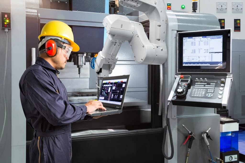
1. Optimizing CNC Machine Setup
Proper machine setup is the foundation for both product quality and production efficiency in CNC milling. An inefficient setup can lead to machine downtime, increased cycle times, and inconsistencies in part quality. By standardizing and streamlining the setup process, manufacturers can improve both the consistency and speed of production.
1.1 Accurate Workholding
One of the key factors in achieving high-quality products is ensuring that the workpiece is securely held in place throughout the milling process. Proper workholding minimizes vibrations and misalignment, which can lead to poor surface finish, dimensional inaccuracies, and tool wear.
- Workholding Techniques:
- Precision Vices: Provide secure and repeatable clamping for various workpiece sizes and shapes.
- Clamps and Fixtures: Designed for specific materials and part geometries to enhance stability.
- Modular Fixtures: Allow for quick adjustments and setup changes.
- Automated Clamping Systems: Reduce setup time while maintaining consistent part positioning.
1.2 Tool Calibration and Zero Point Setting
Calibrating tools and setting the zero point accurately are crucial for ensuring that all cuts are made in the correct position. Incorrect tool offsets or poor calibration can result in part misalignment, affecting the entire batch’s quality.
- Automated Tool Calibration:
- Real-Time Measurement: Tools are measured for length, diameter, and wear before machining begins.
- Reduction of Manual Errors: Ensures consistent tool positioning and minimizes setup variability.
- Zero Point Setting:
- Accurate Reference Points: Establish precise starting points for machining operations.
- Consistent Part Alignment: Ensures uniformity across all produced parts.
2. Using Advanced Tooling and Cutting Strategies
The tools used in CNC milling significantly impact product quality and production efficiency. Choosing the right tools and cutting strategies is essential to optimizing material removal rates, reducing tool wear, and ensuring consistent quality across batches.
2.1 High-Performance Cutting Tools
Using advanced cutting tools, such as carbide, ceramic, or diamond-coated tools, can enhance performance and reduce tool wear, particularly when machining hard materials like titanium or stainless steel. These tools offer greater durability, allowing for faster cutting speeds and longer tool life.
- Carbide Tools:
- Hardness and Durability: Ideal for machining hard materials.
- High Cutting Speeds: Enable efficient material removal.
- Coated Tools:
- Titanium Nitride (TiN): Reduces friction and extends tool life.
- Diamond Coatings: Provide extreme wear resistance for abrasive materials.
2.2 Multi-Tool Machining
In complex parts production, utilizing multi-tool setups within the same machine cycle can greatly reduce tool change times and improve overall efficiency. CNC machines with tool changers that automatically switch between multiple tools during a single operation can help streamline the process.
- Tool Changer Optimization:
- Efficient Sequencing: Organize tool paths to minimize the number of tool changes.
- Reduced Cycle Times: Increase production throughput by minimizing downtime between tool changes.
2.3 High-Efficiency Milling (HEM)
High-Efficiency Milling (HEM) is a cutting strategy designed to optimize the balance between tool life and material removal rates. HEM uses lighter radial depths of cut and higher axial depths, enabling tools to remove material more consistently while generating less heat.
- Benefits of HEM:
- Reduced Cycle Times: Faster material removal without compromising tool life.
- Improved Surface Finish: Consistent cutting conditions lead to smoother finishes.
- Extended Tool Life: Lower heat generation minimizes tool wear.
3. Optimizing CNC Programming and Tool Paths
The efficiency and quality of CNC milling operations are heavily influenced by the programming of tool paths. An optimized program ensures that machining operations are completed with minimal tool movement, reducing cycle times and improving precision.
3.1 Efficient Tool Path Planning
Well-planned tool paths help minimize air cutting (non-cutting time), reduce tool wear, and ensure consistent material removal. By using advanced CAM (Computer-Aided Manufacturing) software, operators can generate optimized tool paths that maximize material removal rates and minimize unnecessary movements.
- Adaptive Tool Paths:
- Dynamic Adjustments: Maintain a constant load on the tool by adjusting tool paths in real-time.
- Reduced Tool Stress: Minimize tool deflection and extend tool life.
- 5-Axis CNC Programming:
- Simultaneous Multi-Directional Movement: Reduce the need for repositioning the workpiece.
- Improved Precision: Achieve tighter tolerances and complex geometries with ease.
3.2 G-Code Optimization
G-code, the programming language used to control CNC machines, can be fine-tuned to improve machining performance. Optimizing G-code includes adjusting feed rates, spindle speeds, and tool engagement angles to achieve a balance between cutting forces and cycle times.
- G-Code Simulation:
- Pre-Machining Verification: Identify potential issues such as tool collisions or inefficient paths.
- Error Reduction: Refine programs to minimize the risk of machining errors during production.
4. Implementing Automation in CNC Milling
Automation can greatly enhance both production efficiency and product quality by reducing human intervention, minimizing errors, and enabling continuous production. Integrating automated processes within CNC milling operations can streamline workflows and ensure consistent results across batches.
4.1 Robotic Tool and Workpiece Handling
Automating the loading and unloading of workpieces or tools reduces manual labor and the risk of human error. Robotic arms or automated workpiece changers can ensure that CNC machines operate continuously without downtime, especially during lights-out manufacturing.
- Lights-Out Manufacturing:
- Unattended Operation: Machines run 24/7 without the need for human supervision.
- Increased Utilization: Maximize machine uptime and production capacity.
4.2 Automated Tool Monitoring
Automated tool monitoring systems track the condition of cutting tools in real-time, ensuring that worn or broken tools are replaced before they cause defects in parts. These systems reduce downtime caused by tool failure and help maintain consistent quality.
- Tool Wear Detection:
- Real-Time Adjustments: Automatically adjust feed rates or cutting speeds based on tool condition.
- Proactive Maintenance: Schedule tool replacements before failures occur.
5. Real-Time Monitoring and Feedback Systems
Real-time monitoring of CNC milling operations allows manufacturers to quickly identify issues that may affect product quality or efficiency. Feedback systems that track key performance indicators (KPIs) such as tool wear, spindle load, and vibration levels can provide valuable insights for optimizing processes.
5.1 Machine Condition Monitoring
Monitoring the condition of the CNC machine itself, including its spindle, motors, and lubrication systems, can help prevent breakdowns and ensure optimal performance. Real-time alerts allow operators to address issues before they lead to costly downtime or defective parts.
- Vibration and Temperature Sensors:
- Early Issue Detection: Identify misalignments or excessive heat generation.
- Preventative Actions: Perform maintenance before severe damage occurs.
5.2 Data-Driven Process Optimization
By collecting and analyzing data from the CNC machine during production, manufacturers can identify trends and make informed decisions to improve efficiency and product quality. This data can be used to optimize tool paths, adjust feed rates, and fine-tune machine settings for better performance.
- Predictive Maintenance:
- Failure Prediction: Use data analytics to forecast when machine components are likely to fail.
- Scheduled Repairs: Perform maintenance proactively to avoid unexpected downtime.
6. Quality Control and Inspection Integration
Integrating quality control and inspection processes directly into CNC milling operations can help improve part accuracy and reduce the time spent on post-production inspection. By incorporating in-process inspections, manufacturers can detect issues early and correct them before a full batch of defective parts is produced.
6.1 In-Process Inspection
In-process inspection systems, such as on-machine probing, allow for real-time measurement of critical part dimensions during machining. These systems can automatically adjust tool paths or stop the machine if deviations are detected, ensuring that parts meet specifications throughout the production run.
- On-Machine Probing:
- Continuous Verification: Measure features like hole positions, surface flatness, and part dimensions during machining.
- Immediate Corrections: Adjust machining parameters in real-time based on inspection results.
6.2 Coordinate Measuring Machines (CMMs)
Coordinate Measuring Machines (CMMs) are often used after CNC milling to verify that parts meet dimensional specifications. By integrating CMM inspections into the production workflow, manufacturers can quickly verify part quality and make adjustments to the milling process as needed.
- Automated CMMs:
- High-Speed Measurements: Perform rapid inspections to keep up with production rates.
- Data Integration: Use inspection data to inform and refine machining parameters for future batches.
Key Strategies for Improvement:
- Optimize Machine Setup: Ensure accurate workholding and tool calibration for consistent part quality.
- Advanced Tooling: Utilize high-performance cutting tools and implement multi-tool machining to enhance efficiency.
- Efficient Programming: Develop optimized tool paths and fine-tune G-code for better performance.
- Automation: Integrate robotic handling and automated tool monitoring to reduce downtime and improve consistency.
- Real-Time Monitoring: Implement condition monitoring and data-driven optimization for proactive maintenance and process refinement.
- Integrated Quality Control: Incorporate in-process inspections and automated CMMs to maintain high standards and reduce rework.
By meticulously refining these aspects of CNC milling operations, manufacturers can ensure high-quality outcomes, maximize productivity, and maintain a competitive edge in the global manufacturing landscape.
How to Maintain and Service a CNC Milling Machine?
CNC milling machines are essential for modern manufacturing, providing the precision, efficiency, and repeatability needed to produce high-quality parts. However, to ensure these machines remain accurate and productive, they require regular maintenance and servicing. Neglecting maintenance can lead to breakdowns, reduced machine accuracy, increased downtime, and costly repairs. Proper maintenance not only extends the life of a CNC milling machine but also improves its performance and reduces the total cost of ownership.
In this section, we will cover key aspects of CNC milling machine maintenance, including daily, weekly, monthly, and annual tasks. We will also discuss common issues that can arise if maintenance is neglected and provide tips on creating an effective maintenance schedule. By following these guidelines, manufacturers can ensure their CNC milling machines remain in peak working condition.
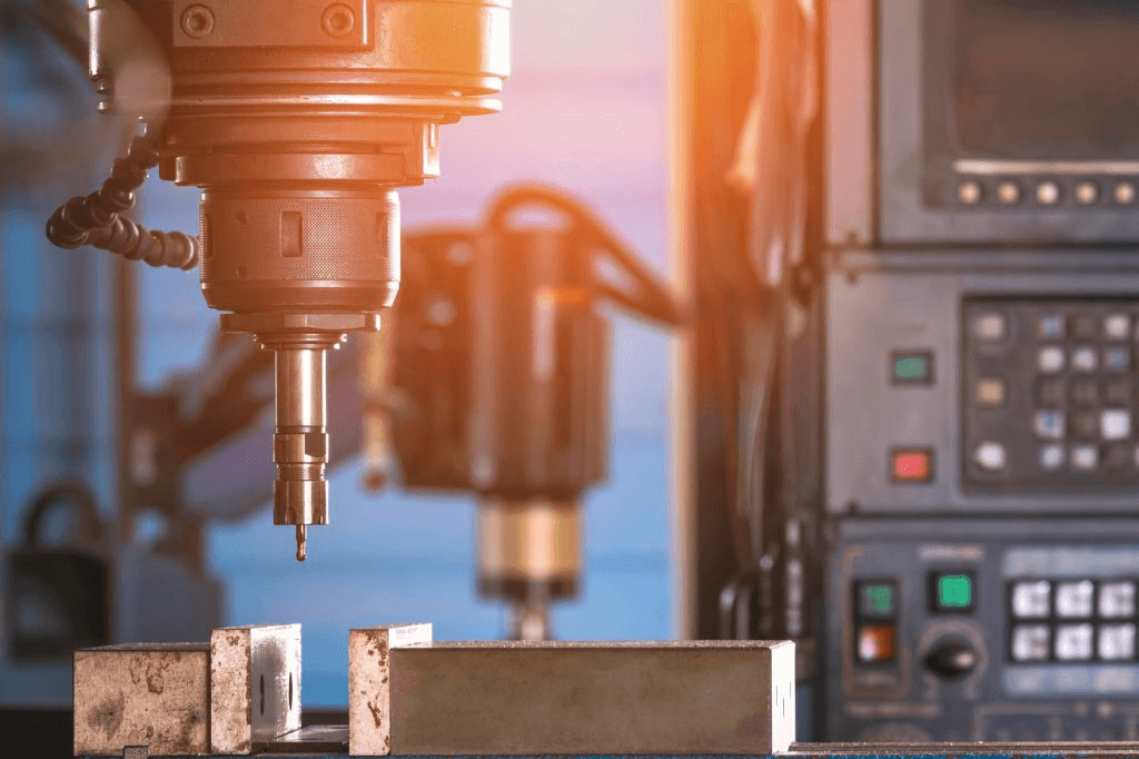
1. The Importance of Regular Maintenance
Before diving into specific maintenance tasks, it is essential to understand why regular maintenance is critical for CNC milling machines.
1.1 Preventing Unplanned Downtime
Unplanned downtime can be one of the most expensive challenges for manufacturers. When a CNC milling machine breaks down unexpectedly, production comes to a halt, which can lead to delays, missed deadlines, and loss of revenue. Regular maintenance can identify and address potential issues before they become major problems, reducing the risk of unplanned downtime.
1.2 Maintaining Accuracy and Precision
CNC milling machines rely on their ability to execute precise movements to create accurate parts. Over time, wear and tear can affect the machine’s components, such as the spindle, lead screws, or bearings, causing misalignments or inaccuracies. Regularly checking and servicing these components ensures that the machine remains accurate and reliable.
1.3 Extending Machine Lifespan
Like any piece of equipment, a CNC milling machine has a finite lifespan. However, with proper maintenance, that lifespan can be significantly extended. Regular servicing helps prevent excessive wear, corrosion, and damage, allowing the machine to operate efficiently for many years.
2. Daily Maintenance Tasks
Daily maintenance tasks are simple and quick but are essential for keeping the CNC milling machine in good condition.
2.1 Cleaning the Machine
Keeping the machine clean is one of the most basic maintenance tasks. Dust, debris, and coolant can accumulate on the machine’s surfaces, in the tool holder, and around moving parts. This buildup can lead to overheating, wear, and malfunction if left unaddressed.
- Steps:
- Use a soft cloth or brush to clean the machine’s exterior and wipe down surfaces.
- Clean the tool holder, spindle, and work area of any chips or debris.
- Ensure that any coolant spills or buildup are cleared to prevent corrosion.
2.2 Checking Lubrication Systems
CNC machines require regular lubrication to reduce friction between moving parts, prevent overheating, and avoid excessive wear. Lubrication systems should be checked daily to ensure they are functioning correctly.
- Steps:
- Inspect the lubrication system to ensure that oil or grease is being distributed to all necessary components.
- Refill the lubricant reservoir if levels are low.
- Check for any signs of leaks or blockages in the lubrication pathways.
2.3 Inspecting Air Filters and Coolant Levels
Air filters prevent dust and debris from entering the machine’s internal components, while coolant helps regulate temperature and prevent overheating during machining operations.
- Steps:
- Check the air filters daily to ensure they are clean and functioning correctly. Replace or clean clogged filters as needed.
- Inspect coolant levels and top them up if necessary.
- Ensure that the coolant is free from contamination and replace it according to the manufacturer’s recommendations.
3. Weekly Maintenance Tasks
Weekly maintenance tasks are more thorough than daily checks but are equally important for preventing wear and tear on the machine.
3.1 Checking for Loose Bolts and Fasteners
Vibration and regular use can cause bolts, screws, and other fasteners to loosen over time. Loose fasteners can lead to poor machine performance and even damage components.
- Steps:
- Inspect the machine for loose bolts, screws, or other fasteners, especially around the spindle, motor mounts, and workholding devices.
- Tighten any that may have come loose using the appropriate tools.
- Verify that all connections remain secure after tightening.
3.2 Inspecting Tool Holders and Spindle Alignment
Tool holders and spindle alignment are critical for ensuring accurate machining. Misaligned spindles or worn tool holders can lead to poor surface finishes, tool breakage, and inaccurate cuts.
- Steps:
- Check the tool holders for wear or damage and replace them if necessary.
- Use a dial indicator to verify the alignment of the spindle with the machine’s axes.
- Adjust the spindle alignment as needed to maintain precision.
3.3 Cleaning the Chip Conveyor
The chip conveyor removes waste material from the work area during machining. A clogged or malfunctioning conveyor can cause chips to accumulate, leading to poor machine performance.
- Steps:
- Inspect the chip conveyor for any blockages or malfunctioning components.
- Clean out accumulated chips and debris from the conveyor.
- Ensure that the conveyor is functioning smoothly and efficiently.
4. Monthly Maintenance Tasks
Monthly maintenance tasks are more in-depth and help identify issues that may not be immediately apparent during daily or weekly checks.
4.1 Inspecting the Electrical System
The electrical system is the lifeblood of the CNC machine, powering motors, sensors, and other critical components. Regular inspections of the electrical system can prevent issues such as short circuits, power failures, or sensor malfunctions.
- Steps:
- Inspect electrical cables, connectors, and wiring for signs of wear, fraying, or corrosion.
- Ensure that all connections are tight and that there are no exposed wires.
- Check for any signs of overheating or burning near electrical components and address issues promptly.
4.2 Checking the Machine’s Calibration
Over time, the machine’s calibration can drift, affecting its accuracy and precision. Monthly calibration checks ensure that the machine is producing parts within the required tolerances.
- Steps:
- Use calibration tools such as gauges, dial indicators, or laser alignment systems to verify the machine’s accuracy in different axes.
- Adjust settings or recalibrate as necessary to bring the machine back within tolerance.
- Document calibration results and adjustments for future reference.
4.3 Testing Safety Features
Safety features such as emergency stop buttons, safety interlocks, and door sensors are essential for protecting operators and the machine itself. Testing these features regularly ensures they function correctly in the event of an emergency.
- Steps:
- Test the emergency stop button to ensure it halts machine operation immediately.
- Verify that safety interlocks and door sensors are functioning properly.
- Replace or repair any malfunctioning safety devices promptly.
5. Annual Maintenance Tasks
Annual maintenance tasks are comprehensive and involve inspecting and servicing the machine’s core components. These tasks are often more time-consuming but are crucial for long-term machine reliability.
5.1 Replacing Worn Components
Over the course of a year, certain components of the CNC milling machine may become worn or damaged due to regular use. Replacing these components before they fail is essential for maintaining the machine’s performance.
- Steps:
- Inspect critical components such as lead screws, bearings, seals, and belts for signs of wear.
- Replace any parts that show signs of wear or are nearing the end of their service life.
- Use manufacturer-recommended replacement parts to ensure compatibility and performance.
5.2 Conducting a Full Machine Inspection
A full machine inspection should be carried out annually to assess the overall condition of the CNC milling machine. This inspection covers everything from mechanical components to software and control systems.
- Steps:
- A trained technician should perform a thorough inspection, checking the alignment of the machine, the condition of moving parts, and the performance of the control system.
- Test the machine’s software and control systems to ensure they are operating correctly.
- Address any identified issues through repairs or part replacements.
5.3 Updating Software and Firmware
Many CNC machines operate with sophisticated software and firmware that controls their functions. Updating the machine’s software and firmware ensures it operates with the latest features and bug fixes, improving overall performance.
- Steps:
- Check for any available updates to the machine’s control software or firmware.
- Follow the manufacturer’s instructions for safely installing updates.
- Verify that the machine operates correctly after updating software or firmware.
6. Common Issues and Troubleshooting
Even with regular maintenance, CNC milling machines may occasionally experience issues that require troubleshooting. Understanding common problems and how to address them can help minimize downtime and maintain production efficiency.
6.1 Excessive Tool Wear
Excessive tool wear is often a sign of improper cutting parameters or poor lubrication. Addressing the root cause of tool wear can prevent further damage to the machine and improve part quality.
- Solution:
- Review and adjust cutting speeds, feeds, and coolant flow to ensure optimal conditions for the tool.
- Ensure that the lubrication system is functioning properly and that tools are calibrated correctly.
- Use higher-quality or coated tools suitable for the material being machined.
6.2 Machine Vibration
Vibration can result from misalignment, loose components, or worn bearings. Excessive vibration can lead to poor surface finish, tool breakage, and inaccurate machining.
- Solution:
- Check for loose bolts or fasteners and tighten them as needed.
- Inspect the machine’s spindle and bearings for wear, and replace any components contributing to vibration.
- Ensure proper workholding and balance of the workpiece to minimize vibrations during machining.
6.3 Poor Surface Finish
A poor surface finish is often caused by worn tools, improper feed rates, or misaligned spindles. Resolving these issues will improve the finish and accuracy of machined parts.
- Solution:
- Replace worn tools and ensure that the spindle is properly aligned.
- Adjust the feed rate and cutting speed to optimize the surface finish.
- Verify tool geometry and ensure that the correct tool is being used for the operation.
7. Creating a CNC Maintenance Schedule
To ensure that all maintenance tasks are completed on time, manufacturers should create a comprehensive maintenance schedule. This schedule should outline daily, weekly, monthly, and annual tasks and assign responsibilities to specific personnel.
7.1 Using Maintenance Management Software
Many manufacturers use maintenance management software to track and schedule maintenance tasks. These tools provide reminders for upcoming tasks, log completed maintenance activities, and track the condition of the machine over time.
- Benefits:
- Automated Reminders: Ensure that no maintenance tasks are overlooked.
- Record Keeping: Maintain detailed logs of all maintenance activities for accountability and reference.
- Condition Tracking: Monitor the machine’s condition and predict maintenance needs based on usage data.
7.2 Training Maintenance Personnel
Properly trained maintenance personnel are essential for performing maintenance tasks correctly and efficiently. Ensure that all personnel responsible for maintaining CNC machines are trained on the specific maintenance requirements of each machine.
- Steps:
- Comprehensive Training Programs: Provide training on machine operation, maintenance procedures, and troubleshooting techniques.
- Ongoing Education: Keep maintenance staff updated with the latest advancements in CNC technology and maintenance best practices.
- Certification: Encourage certifications from recognized CNC training programs to ensure high competency levels.
7.3 Establishing Clear Responsibilities
Assign specific maintenance tasks to designated personnel to ensure accountability and consistency.
- Steps:
- Role Definition: Clearly define the roles and responsibilities of each maintenance team member.
- Task Allocation: Assign daily, weekly, monthly, and annual tasks based on expertise and availability.
- Performance Monitoring: Regularly review maintenance performance to ensure tasks are being completed correctly and on schedule.
Key Maintenance Strategies:
- Optimize Machine Setup: Ensure accurate workholding and tool calibration for consistent part quality.
- Advanced Tooling: Utilize high-performance cutting tools and implement multi-tool machining to enhance efficiency.
- Efficient Programming: Develop optimized tool paths and fine-tune G-code for better performance.
- Implement Automation: Integrate robotic handling and automated tool monitoring to reduce downtime and improve consistency.
- Real-Time Monitoring: Use condition monitoring and data-driven optimization for proactive maintenance and process refinement.
- Integrated Quality Control: Incorporate in-process inspections and automated CMMs to maintain high standards and reduce rework.
- Comprehensive Training: Ensure maintenance personnel are well-trained and knowledgeable about the specific requirements of CNC milling machines.
- Use Maintenance Software: Leverage maintenance management tools to track, schedule, and document maintenance activities efficiently.
By meticulously refining these aspects of CNC milling operations, manufacturers can ensure high-quality outcomes, maximize productivity, and maintain a competitive edge in the global manufacturing landscape.
FAQ
- Is CNC Milling Suitable for Small Batch Production?
Yes, CNC milling is highly suitable for small batch production. It offers high precision and flexibility, allowing for rapid changes in design without requiring expensive tooling setups. This makes it cost-effective for smaller runs, especially for customized parts. - What Factors Affect the Cost of CNC Milling?
Key cost factors include material type, part complexity, machining time, tool wear, and setup costs. Additional factors like surface finish requirements and tolerances also impact overall cost. - How to Reduce Tool Wear in CNC Milling?
To reduce tool wear, use appropriate cutting speeds and feed rates, apply proper coolant or lubrication, and choose high-quality, coated tools. Regular maintenance of tools and machines is also crucial. - What’s the Difference Between CNC Milling and CNC Turning?
CNC milling uses rotary cutting tools to remove material from a stationary workpiece, while CNC turning rotates the workpiece and uses stationary cutting tools. Milling is better for complex, flat, or 3D parts, while turning is ideal for cylindrical parts. - How to Choose the Right CNC Milling Machine?
Choose based on the material to be machined, required precision, machine size, axis count (3, 4, or 5-axis), tool capacity, and budget. Consider software compatibility and after-sales support. - How Long Does a CNC Milling Tool Last?
Tool life varies based on material, tool quality, cutting speeds, and maintenance. For standard carbide tools, lifespan is usually between 20 to 30 hours of continuous cutting, but it can be extended with proper usage and care. - What Tolerances Can Be Achieved with CNC Milling?
CNC milling typically achieves tolerances between ±0.001″ to ±0.005″ (±0.025 mm to ±0.127 mm), depending on the material and part design. - What Are the Best Practices for CNC Milling Aluminum?
Use sharp tools, appropriate speeds, and feeds to prevent tool wear and ensure smooth cutting. Apply coolant to reduce heat and avoid chip buildup. Use softer alloys for easier machining. - How to Minimize Vibrations During CNC Milling?
Minimize vibrations by ensuring proper tool clamping, reducing spindle speeds, using shorter tools, and improving machine rigidity. Avoid overextending the tool from the holder. - What Causes Burrs in CNC Milling and How to Avoid Them?
Burrs are caused by improper cutting parameters or worn tools. Avoid burrs by using sharp, coated tools, optimizing speeds, and ensuring proper tool paths. Post-process deburring may be necessary. - What Are the Best Materials for CNC Milling Tools?
The best materials for CNC tools include carbide, high-speed steel (HSS), and ceramic for hard materials. Coated tools with TiN or diamond coatings offer improved wear resistance. - How to Optimize CNC Milling for High-Precision Parts?
To optimize for precision, use high-quality machines, sharp tools, tight calibrations, and proper lubrication. Ensure optimal cutting speeds, minimal tool deflection, and regular machine maintenance. - How to Troubleshoot CNC Milling Programming Errors?
Check G-code for syntax errors, ensure proper tool paths, verify workpiece coordinates, and use simulation software to catch issues before machining. Cross-check with the design model. - What Safety Measures Should Be Taken When Using CNC Milling Machines?
Operators should wear safety goggles, avoid loose clothing, use machine guards, and follow lockout procedures. Regular machine inspection and following safety protocols are essential. - What Are the Limitations of CNC Milling Compared to Other Machining Methods?
CNC milling is less efficient for cylindrical parts and may not be ideal for high-volume production due to longer setup times. Complex internal geometries can also be difficult to machine without additional processes.